Search filter
69 results found
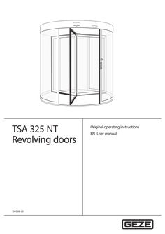
User manual TSA 325 NT revolving doors
… operating instructions EN User manual TSA 325 NT Table of contents Supplied system … 1 About these instructions … 2 Safety instructions … Instructions for safe operation … Further technical safety instructions … 4 Operation … Door in normal operation … Selecting the operating mode … Burglar-resistant o RC2 Manual revolving door o M Underfloor drive o UFA With automatic positioning device o P Manual night-time closer o NV Automatic revolving door o A Automatic night-time closer o ANV Servo revolving door o S Internal manual night-time closer o INV All-glass o GG Internal automatic night-time closer o IANV Example: TSA 325 NT A3 NV BO = revolving door TSA 325 NT automatic drive with … leaves, with manual nighttime closer and break-out function … About these instructions About these instructions Warning notices Warning notices are used in these instructions to warn you of personal injury and property damage. XX Always read and observe these warning notices. XX Observe all measures marked with the warning symbol and warning word. Warning symbol Warning word Meaning CAUTION Danger to persons. Non-compliance can result in minor to medium injuries. Further symbols and illustrations Important information and technical notes are highlighted to explain correct operation. Symbol Meaning means “important note”; information about avoiding property damage means “additional Information” The user's attention should be drawn to important addition information. There is no danger to persons or property, but it is particularly useful to read the additional information carefully. XX … Symbol for an action: This means you have to do something. XX If there are several actions to be taken, keep to the given order. Product liability In compliance with the liability of the manufacturer for his products as defined in the German “Product Liability Act”, compliance with the information contained in this brochure (product information and intended use, misuse, product performance, product maintenance, obligations to provide information and instructions) must be ensured. Failure to comply releases the manufacturer from his statutory liability. To ensure personal safety, it is important to follow these safety instructions. These instructions must be kept. … Safety instructions … Instructions for safe operation àà Failure to observe the instructions in this handbook may result in damage to the equipment or personal injury. àà The door may only be used for the movement of persons. àà This appliance can be used by children aged from … years and above and persons with reduced physical, sensory or mental capabilities or lack of experience and knowledge if they are supervised, or if they have been given instruction concerning use of the appliance in a safe way and understand the hazards involved. However, this does not generally exclude such persons from using the door on which the drive is installed. àà Children shall not play with the appliance. àà Cleaning and maintenance shall not be carried out by children without supervision. àà The door system must be unplugged from the mains connection during maintenance and cleaning work. àà No persons may pass through the door system during repair or maintenance work. … TSA 325 NT General safety notices Carefully read and abide by this user manual before commissioning the door. Always observe the following safety instructions: XX Make sure that the relevant accident prevention regulations and standard EN 16005 are observed. XX Observe any relevant additional national and European directives. XX Operating, maintenance and repair conditions specified by GEZE must be observed. àà Maintenance and repair work may only be performed by properly trained personnel authorised by GEZE. The protective conductor must be connected. àà Only trained, GEZE-authorised personnel may open the cover. àà GEZE shall assume no liability for damage caused by unauthorised changes to the system. àà The door system is solely suitable for use in entrances and interior areas of pedestrian traffic in commercial plants and public areas. àà The owner is responsible for safe operation of the system. If safety equipment is misaligned, causing it to no longer fulfil its intended purpose, further operation is no longer permissible. Inform the service technician immediately. àà In accordance with Machine Directive 2006/42/EC and EN 16005, a safety analysis must be performed and the door system identified in accordance with CE Identification Directive 93/68/EEC before the door system is commissioned. àà If there are any glass breakages (ceiling, leaf or drum wall), put the door out of use immediately and use suitable measures to prevent anyone entering the area (e.g. barrier tape). Notify a service technician. àà The door may stop unexpectedly if a safety function is triggered. It is possible that persons may walk into a stopped door leaf and hit it. àà If possible, the glass on the drum wall and side-hung leaf must be labelled at eye level through appropriate measures, to prevent persons from running into it. àà When switching over to night mode, the operator must ensure that no persons have been trapped in the door system. … Further technical safety instructions àà The flooring used under the area of the side-hung leaf on a revolving door may have a maximum unevenness of … mm. àà To ensure user safety, sufficient ambient lighting must be available. àà The setting for the revolving speed of the door system must be adjusted to the expected users of the system. It may be necessary to reduce the speed. àà Persons may stand in front of and inside the door system only to pass from one area to another area. àà In general, no one may stand on the roof of the door system. … Intended use The door system is solely suitable for use in entrances and interior areas of pedestrian traffic in commercial plants and public areas. Make sure the door system is used for this purpose during operation. Heed the following points when using the door system: XX Make sure that the electrically powered turnstile is not accelerated manually. XX Adapt the walking speed of the door system. XX Make sure that the opening is large enough for entering and leaving the door system. XX Do not stand still in the door system or change directions. XX Ensure sufficient distance to the drum wall and the side-hung casement. XX Do not stand still in the direct vicinity of the door entrance or exit. XX Do not enter the door carrying bulky objects or pushing a trolley (e.g. shopping trolley). XX Make sure children are always accompanied when they enter the door system. XX Keep children at play away from the door system. XX Keep animals on a short lead or carry them. The door system must be used for the intended purpose so that the revolving door safety sensors do not unexpectedly slow or stop the door system in operation. In certain conditions, changing weather conditions (wind, snow, rain, bright sunshine) can cause brief interruptions or standstill of the door system. This is not a fault, rather it is to guarantee user safety. … TSA 325 NT Description Deactivation of the escape and rescue route function àà If the operator switches to “NIGHT” mode and locks the turnstile or closes a night-time closer, the revolving door will no longer be available as an escape route. àà The "NIGHT" mode of operation is not a defined operating mode according to the guidelines on automatic sliding doors in escape and rescue routes (AutSchR). àà Only authorised persons may change the mode of operation with the key push button at the programme switch. àà The operator may only switch to "NIGHT" if the emergency exit route is no longer used, i.e. people are no longer in the building or an escape and rescue chart indicates other emergency exit routes for this time period. … Structure The operating elements are arranged differently depending on the situation. For technical reasons, we cannot show all of the possibilities here. The door system shown is only a schematic diagram. … Keypad programme switch to switch modes of operation and to display error codes on the door system. … Optional; key switch to protect the programme switch against unauthorised operation. … TSA 325 NT Explanation Rubber strip on the right post of the door system. When the rubber strip is pressed, this triggers a stop of the door system. After the rubber strip is released, the drive restarts independently after a set pause time. Rubber strip on the bottom leaf profile. When the rubber strip is pressed, this triggers a stop of the door system. After the rubber strip is released, the drive restarts independently after a set pause time. Rubber strip on the exterior vertical door leaf profile. When the rubber strip is pressed, this triggers a stop of the door system. After the rubber strip is released, the drive restarts independently after a set pause time. Optional; sticker on the door leaf when using doors with break out door fittings in emergency exit systems. Optional; use with revolving doors with a diameter over 3,000 mm. The safety sensor reduces the revolving speed when the door leaf approaches a person or triggers a stop of the door leaf. GEZE door variants Door variant Manual doors Manual doors with speed limiter Manual doors with automatic positioning device Servo doors Fully automatic revolving doors … Special feature Doors without safety function, exclusively for manual use The max. speed of the revolving door is limited by a safety mechanism in the door. Once it has been passed, the manual door is moved motor-driven to its initial/end position at very low speed. The programme switch must be set to the manual mode of operation. Increased comfort compared with a manual door thanks to automatic starting of the turnstile with radar movement detector. In order to reach walking speed, the turnstile can be overridden by hand. After the door has been passed, it revolves slowly to the final position. The speeds are limited. The programme switch must be set to the manual mode of operation. Activation via movement detector. Electromechanical drive with two pre-adjustable speeds. The revolving movement starts automatically. Special feature The drum walls do not have a frame at the top or bottom and the door has a glass roof. The drum walls have a frame and the door has a glass roof. The side-hung casements can be broken out in any position by pressing the outer edge of the leaf. When a leaf is broken out, the drive is switched off immediately. The door leaves can be engaged again by hand. Then the door continues revolving until it reaches its end position. Burglar-resistant fitting system tested in accordance with DIN EN 1627 1630. Special version of the night-time closer, drum walls and roof. TSA 325 NT … Operation … Door in normal operation Operation GEZE revolving doors can be operated with special control elements, which deviate from the behaviour described here. Please ask the service technician responsible for information on the special control elements which are installed. During normal door operation the door revolves as long as persons are within the range of influence of the sensors. What happens? An activation device (push button, switch or movement detector) is triggered. The safety sensor (mobile safeguarding device) triggers because an object has been detected between the leaves. Safety sensor (front post safety sensor) is triggered when the door revolves. Safety sensor on the side element (post safety sensor) is triggered. Safety sensors on the leaf (draw-in protection) touch an obstruction and are triggered. … What does the door do? The door begins to revolve. The door slows down to a standstill if necessary. As soon as the passing leaf comes nearer than the preset danger distance, the door slows down to a standstill. The door slows down to a standstill. The door slows down to a standstill. Additional door functions In addition to the keypad programme switch, various additional functions control the door manually via switches or push buttons. Which switch/push button? Emergency stop switch Key push button of the keypad programme switch Contact sensor “Authorised” (e.g. outside key push button) Activation button Push pad Key switch for night-time closer … What does the switch/push button do? The door brakes to a standstill and can be revolved freely. If a key push button is connected to the keypad programme switch, the operation of the keypad programme switch can be locked or released with it. The door unlocks and revolves in accordance with the number of sectors set and lets the person pass. The door revolves at full speed The door slows and revolves at reduced speed When the key switch is activated, the night-time closer sliding door will open or close. XX Ensure that the night-time closer is either completely open or completely closed. Selecting the operating mode Change the mode of operation once daily for doors with a positioning device / servo or for fully automatic doors. When the mode of operation is changed, internal tests are completed to ensure fault-free operation. XX The system operating mode is selected and the corresponding programme is displayed at the keypad programme switch. The operating mode is changed by pushing the or buttons. Keypad programme switch TPS-KDT The current operating mode is indicated by permanent illumination of the corresponding LED. The TPS-KDT indicates the actual operating mode, even if the operating mode is changed via another operating mode input (e.g. additionally fitted switches or GLT system). … Operation TSA 325 NT The keypad programme switch is accessible for everyone. Therefore we recommend the use of an additional key push button in order to block the keypad programme switch. The keypad programme switch is only enabled while the key push button is operated. Changing the operating mode of the TPS can also be protected by setting parameters for a password to prevent the operating mode being changed by unauthorised persons. The password can only be set and changed by a service technician. The password for operating the keypad programme switch (TPS-KDT) has … 99). The arrow keys are used for entry. The factory setting is 00 (released). Operating status Automatic TPS-KDT Explanatory notes All the connected pulse generators are active in the “Automatic” operating mode. Revolving speed and time delay can be set. When activated by a movement detector the door accelerates to the set automatic speed, continues to revolve at this speed and stops in the target position after a preset number of sectors. The following special functions are possible in the “Automatic” operating mode: Summer operation The turnstile stands still without activation. When activated for the first time, the revolving door accelerates to automatic speed. After that the revolving door revolves at the automatic speed for a number of sectors that can be set and then slows to the run-on speed. The revolving door revolves at the slow speed for a set time delay and then stops in the next target position. This operating mode is particularly suitable for creating an welcoming atmosphere. If the time delay is set to endless, the revolving door revolves permanently. Winter operation The turnstile stands still without activation. When activated, the revolving door accelerates to the automatic speed. After that the revolving door revolves at the automatic speed for a number of sectors that can be set and then stops in the target position. In “Automatic” operating mode, alteration between summer and winter operation can be affected by simultaneously pressing the buttons and . If winter operation is selected, the LED “Winter” is illuminated in the TPS-KDT. Exit only Manual Night mode … Activation of push pad (optional) A switch with a wheelchair symbol is located on the door. When this switch is activated, the door brakes and revolves at the set disabled access speed. This speed is specified for the set number of sectors. In the “exit only” operating mode the door is only activated via the internal movement detector, then revolves for a set number of sectors at automatic speed and then stops again in the target position. The turnstile can be rotated freely in manual operation. If no further functions are set, the “Manual” operating mode is identical with the “Off” operating mode. The following options can be set: àà An automatic positioning device returns the door to the target position at slow speed after passing has been completed. àà Safety devices can be activated. àà The speed limiter can be activated. àà Prescribed mode of operation for revolving doors with automatic positioning device and servo revolving doors. The following options for locking can be built into the system in order to lock it in the “Night” operating mode: No locking If the revolving door does not have a locking function, it can be revolved manually in the “Night” operating mode. TSA 325 NT Operating status Night mode Operation TPS-KDT Explanatory notes Manual locking A rod locking can be used as a manual locking element. A contact used to monitor the locking operating mode is installed. Unlock Lock XX Disengage lock. XX Disengage lock. XX Unlock leaf. XX Lock leaf. XX Engage lock. XX Engage lock. The leaf locking mechanism may also function as mirror-inverted for the all-glass version (AG). To lock the door manually: XX Select the “Night” operating mode at the keypad programme switch. The Night LED flashes on the TPS-KDT. The door revolves automatically to the locking position. XX Lock the locking device manually. The Night LED switches to continuous light. Unlocking the door manually: XX Unlock the locking device manually. The Night LED of the TPS-KDT switches to flashing. XX Set the desired operating mode on the TPS-KDT. The LED indicates the operating mode. Locking device with disc brake A disc brake can be used to lock the revolving door. When the power supply is interrupted, the brake is opened. The revolving door can then be revolved manually. It is not suitable for a revolving door with break-out function. Locking the door: XX Select the “Night” operating mode on the TPS-KDT. The Night LED flashes on the TPS-KDT. The door revolves automatically to the locking position. The disc brake is activated. The Night LED switches to continuous light. Unlocking the door: XX Select the desired operating mode on the TPS-KDT. The disc brake is released. The new operating mode is active and is displayed on the TPS-KDT. … Operation Operating status Night mode TSA 325 NT TPS-KDT Explanatory notes Electromagnetic lock One or two electromagnetic locks can be used to lock the revolving door. A locked door remains locked when the power fails. An unlocked door remains unlocked when the power fails. In the case of a power failure the lock can be unlocked by means of a built-in battery. XX Select the “Night” operating mode at the keypad programme switch. The door moves to the end position and locks automatically. Option: Revolving door suitable for use in escape and rescue routes. Only with the break out variant (BO) with a separate key push button for locking. XX During the slow movement into the end position, press the key operated button and keep it pressed. The door locks automatically in the end position. XX Release the key operated button again. XX In order to unlock the door, activate the key operated button and switch on the desired operating mode at the button programme switch. Access via the contact sensor authorised (only at revolving doors suitable for use in escape and rescue routes): XX Operate the authorised contact sensor (I think). The door revolves once. XX In order to lock the door hold the authorised contact sensor authorised until the door has locked automatically. Locking in the event of a power failure In order to avoid the danger of persons being locked in, the revolving door may not be entered when the locking bolts are lowered and may only be turned further from the outside. A special locking switch is required for locking and unlocking. Locking with night-time closer The revolving door can be locked with a single leaf or double leaf night-time closer manual or automatic). Manual night-time closer: The procedure is identical to manual locking. Automatic night-time closer: XX Select the “Night” operating mode on the TPS-KDT. The door revolves automatically to the locking position. XX In order to lock the night-time closer, activate the key push button and hold it until the nighttime closer is closed and locked. XX In order to open the night-time closer, activate the switch and hold it until the night locking system is open. XX Select the desired operating mode on the TPS-KDT. When locking the door, the operator must ensure that no persons have become caught in the door system. Off … XX In the “Off” operating mode the motor is switched off and the door can be freely revolved manually . This operating mode is especially suitable for maintenance and cleaning of the door. All activation devices are switched off. Locking/unlocking (optional) For a description of locking/unlocking the door, see Section … “Selecting the operating mode”, Night operating mode. If a revolving door suitable for escape and rescue routes is used, the operator must ensure that the door really is unlocked after it has been unlocked. 10 TSA 325 NT … No mains voltage Behaviour in an emergency CAUTION! Danger of injury caused by crushing! The door leaf may only be snapped into place by trained personnel. XX When re-engaging the breakout leaf, ensure that your fingers do not become stuck on the inner leaf edge. If a revolving door suitable for escape and rescue routes is used, the operator must ensure that the door really is unlocked after it has been unlocked. The door can be stopped via the emergency stop switch and moved manually. Revolving doors with break out system (BO) can be opened in any position by pressing the outer edge of the leaf (< 220 N), clearing a suitable escape route. The drive is switched off immediately after the leaf has been broken out and the turnstile can be revolved manually. … No mains voltage XX If the mains voltage fails (e.g. power failure), check the on-site safety fuse first. State Reaction No mains voltage In “Night” operating mode, the door remains locked as long as a disc brake was not used. In other operating modes, the door coasts to standstill and stops. The door starts again in the previously set operating mode. The door can be revolved manually providing it was not locked. Mains voltage available again Door leaves revolve if there is no active power supply … seconds (several LEDs), alternating with the operating mode (one LED). Up to 20 different fault messages can be displayed. XX Read the fault message, record it and notify the service technician. TPS display ○ ○ ○ ○ ○ ○ ○ ○ ○ ○ ● ● ● ● ● ● ● ● ● ● ● ○ ○ ○ ○ ○ ● ● ● ● ● ○ ○ ○ ○ ○ ○ ● ● ● ● ● ○ ○ ● ● ● ○ ○ ● ● ● ○ ○ ○ ● ● ● ○ ○ ○ ○ ● ○ ● ○ ● ● ● ● ○ ○ ● ○ ● ● ○ ○ ● ○ ● ● ○ ○ Designation ○ ● ● ○ ● ○ ● ○ ● ○ ● ○ ● ○ ● ○ ● ○ ● ○ ○ No operating voltage Drive too hot Position Post safety Motor, rotary encoder, initialisation sensor Emergency stop Draw-in protection (post safety sensor/vertical safety contact strip) Rechargeable battery Frequency converter Mobile safeguarding device(accompanying safety) Alarm Front post safety sensor Disc brake Break out 24 V internal (fuse F1) 24 V external Mains power failure Control unit, motor relay Keypad programme switch Service terminal Locking 11 What to do if...? TSA 325 NT In addition, the following states are displayed: àà Non-taught Winter LED flashes continuously (1 s on, … s off) àà Fault Operating mode displayed for … sec. àà Block active Current operating mode LED flashes once if a key is pressed on the TPS and if the operating mode cannot be switched (key push button not operated or there is a permanent signal at the input DO, AU, LS or NA). … What to do if...? Problem Door revolves very slowly Door does not revolve Cause Floor area soiled Remedy XX Interrupt power supply. XX Clean the affected floor area. XX Remove obstruction and check door manually for smooth Obstruction in travel path movement. Mobile safeguarding device XX Clean safety sensor. is interrupted or misaligned XX Check the setting of the optical safety sensors. XX Revolve the door manually, remove visible obstacles. If no obstaScraping on floor, other mechanical impediment cles are visible, notify a service technician. XX Check movement detector. Movement detector misXX Notify a service technician. aligned or defective XX Select another operating mode. “Night”, “Off” operating mode “Exit only” operating mode XX Select “Automatic” operating mode. Door is locked manually XX Unlock the door. No mains voltage XX See chapter 5, “No mains voltage”. XX Unlock emergency stop switch. XX XX Engage the door leaf again by hand and wait for the door system to start up. Select another operating mode. No mains voltage XX See chapter 5, “No mains voltage”. Obstruction in travel path XX XX Remove the obstacle. Notify a service technician. Change to the “Manual” operating mode and check the movement force manually. If the revolving force is too high, notify a service technician. Check locking in the “Night” operating mode. Unlock the door manually and notify a service technician. Activate the key push button, repeat the unlocking process. XX Activate key switch. XX Request servicing. XX See chapter 6, “Fault messages on the programme switch TPS-KDT”. XX Put the door out of operation immediately and take suitable measures to prevent anyone entering the door (e.g. barrier tape). Notify a service technician. Emergency-stop switch pressed Door leaf has been broken out (BO variant) Door only revolves manually “Off” operating mode Door always revolves only a bit further XX XX Door does not unlock or lock Locking defective (in case of automatic locking) Key push button not activated Programme switch cannot Programme switch be operated is blocked Programme switch is defective Fault messages displayed at Fault in the door system programme switch Glass break Impact on pane (door leaf/drum wall) XX XX XX 12 TSA 325 NT Cleaning and maintenance Carry out a reset/delete the fault memory Use key or to change to the mode of operation OFF (see Section … “Selecting the operating mode”). Press keys and simultaneously for … s. The fault memory with the current faults is deleted. XX Select the desired new mode of operation. XX XX … , “Cleaning”. Monthly: XX Check the lubrication of the floor bearing and re-grease bearings if necessary. If the “Winter” LED on the TPS-KDT keypad programme switch flashes continuously, maintenance is required. GEZE offers maintenance contracts with the following services: àà Inspect and adjust the chain. àà Check the leaf suspension. àà Check the attachment elements for firm seating. àà Performance of miscellaneous adjustment work. àà Performance of operational checks. 13 Disposal … 7) XX Wipe with damp cloth. Do not use a cleaning agent. XX Clean weekly with the vacuum cleaner. XX Clean/vacuum clean at regular intervals. XX Lift up the entrance mat and vacuum clean under it. Inspection by an expert In compliance with standard EN 16005, the safe state of power operated doors must be checked before initial operation and at least once a year by an expert. GEZE offers the following services: Inspection and operational checks of all safety and control equipment in compliance with the requirements in the test log for power-operated windows, doors and gates; Sliding doors and sliding gates ZH 1/ … m/sec 230 V, 50–60 Hz, 350 W 24 V DC, max. 3,5 A 10 mm2 –15 °C to +50 °C Ceiling drive: IP 20 Underfloor operator: IP 54 < 68 dB (A) over 500,000 cycles All rights reserved. These original operating instructions are also available over the GEZE customer portal or at www.geze.com. 15 Germany GEZE GmbH Niederlassung Süd-West Tel. +49 (0) 7152 203 594 E-Mail: leonberg.de@geze.com GEZE GmbH Niederlassung Süd-Ost Tel. +49 (0) 7152 203 6440 E-Mail: muenchen.de@geze.com GEZE GmbH Niederlassung Ost Tel. +49 (0) 7152 203 6840 E-Mail: berlin.de@geze.com GEZE GmbH Niederlassung Mitte/Luxemburg Tel. +49 (0) 7152 203 6888 E-Mail: frankfurt.de@geze.com GEZE GmbH Niederlassung West Tel. +49 (0) 7152 203 6770 E-Mail: duesseldorf.de@geze.com GEZE GmbH Niederlassung Nord Tel. +49 (0) 7152 203 6600 E-Mail: hamburg.de@geze.com GEZE Service GmbH Tel. +49 (0) 1802 923392 E-Mail: service-info.de@geze.com Austria GEZE Austria E-Mail: austria.at@geze.com www.geze.at Hungary GEZE Hungary Kft. E-Mail: office-hungary@geze.com www.geze.hu Scandinavia – Sweden GEZE Scandinavia AB E-Mail: sverige.se@geze.com www.geze.se Baltic States – Lithuania / Latvia / Estonia E-Mail: baltic-states@geze.com Iberia GEZE Iberia S.R.L. E-Mail: info.es@geze.com www.geze.es Scandinavia – Norway GEZE Scandinavia AB avd. Norge E-Mail: norge.se@geze.com www.geze.no Benelux GEZE Benelux B.V. E-Mail: benelux.nl@geze.com www.geze.be www.geze.nl India GEZE India Private Ltd. E-Mail: office-india@geze.com www.geze.in Scandinavia – Denmark GEZE Danmark E-Mail: danmark.se@geze.com www.geze.dk Bulgaria GEZE Bulgaria - Trade E-Mail: office-bulgaria@geze.com www.geze.bg Italy GEZE Italia S.r.l E-Mail: italia.it@geze.com www.geze.it Singapore GEZE (Asia Pacific) Pte, Ltd. E-Mail: gezesea@geze.com.sg www.geze.com China GEZE Industries (Tianjin) Co., Ltd. E-Mail: chinasales@geze.com.cn www.geze.com.cn GEZE Engineering Roma S.r.l E-Mail: italia.it@geze.com www.geze.it South Africa GEZE South Africa (Pty) Ltd. E-Mail: info@gezesa.co.za www.geze.co.za GEZE Industries (Tianjin) Co., Ltd. Branch Office Shanghai E-Mail: chinasales@geze.com.cn www.geze.com.cn GEZE Industries (Tianjin) Co., Ltd. Branch Office Guangzhou E-Mail: chinasales@geze.com.cn www.geze.com.cn GEZE Industries (Tianjin) Co., Ltd. Branch Office Beijing E-Mail: chinasales@geze.com.cn www.geze.com.cn France GEZE France S.A.R.L. E-Mail: france.fr@geze.com www.geze.fr Korea GEZE Korea Ltd. E-Mail: info.kr@geze.com www.geze.com Poland GEZE Polska Sp.z o.o. E-Mail: geze.pl@geze.com www.geze.pl Romania GEZE Romania S.R.L. E-Mail: office-romania@geze.com www.geze.ro Russia OOO GEZE RUS E-Mail: office-russia@geze.com www.geze.ru Switzerland GEZE Schweiz AG E-Mail: schweiz.ch@geze.com www.geze.ch Turkey GEZE Kapı ve Pencere Sistemleri E-Mail: office-turkey@geze.com www.geze.com Ukraine LLC GEZE Ukraine E-Mail: office-ukraine@geze.com www.geze.ua United Arab Emirates/GCC GEZE Middle East E-Mail: gezeme@geze.com www.geze.ae United Kingdom GEZE UK Ltd. E-Mail: info.uk@geze.com www.geze.com GEZE GmbH Reinhold-Vöster-Straße 21–29 71229 Leonberg Germany Tel.: 0049 7152 203
PDF | 374 KB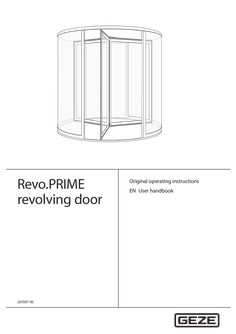
Revo.PRIME revolving door
… operating instructions EN User handbook Revo.PRIME Contents Supplied system … 1 About these instructions … Instructions for safe operation … 4 Operation … Door in normal operation … Selecting the operating status … Burglar-resistant o RC2 Manual revolving door o M Underfloor drive o UFA Manual revolving door with speed limiter o D Manual night-time closer o NV With automatic positioning device o P Automatic night-time closer o ANV Automatic revolving door o A Inside-running manual night-time closer o INV All-glass o GG Internal automatic night-time closer o IANV Example: Revo.PRIME A3 NV BO = Revo.PRIME revolving door automatic drive with … leaves, with manual nighttime closer and break-out function … About these instructions About these instructions Warning notices Warning notices are used in these instructions to warn you of personal injury and property damage. XX Always read and observe these warning notices. XX Observe all measures marked with the warning symbol and warning word. Warning symbol Warning word CAUTION Meaning Danger to persons. Non-compliance can result in minor to medium injuries. Further symbols and illustrations Important information and technical notes are highlighted to explain correct operation. Symbol Meaning means “important note”; Information about avoiding property damage means “additional Information” The user's attention should be drawn to important addition information. There is no danger to persons or property, but it is particularly useful to read the additional information carefully. XX … Symbol for an action: This means you have to do something. XX If there are several actions to be taken, keep to the given order. Product liability In compliance with the liability of the manufacturer for his products as defined in the German “Product Liability Act”, compliance with the information contained in this brochure (product information and intended use, misuse, product performance, product maintenance, obligations to provide information and instructions) must be ensured. Failure to comply releases the manufacturer from his statutory liability. To ensure personal safety, it is important to follow these safety instructions. These instructions must be kept. … Instructions for safe operation àà Failure to observe the instructions in this handbook may result in damage to the equipment or personal injury. àà The door may only be used for the movement of persons. àà This appliance can be used by children aged from … years and above and persons with reduced physical, sensory or mental capabilities or lack of experience and knowledge if they have been given supervision or instruction concerning use of the appliance in a safe way and understand the hazards involved. However, this does not generally exclude such persons from using the door on which the drive is installed. àà Children shall not play with the appliance. àà Cleaning and maintenance shall not be carried out by children without supervision. àà The door system must be unplugged from the mains connection during maintenance and cleaning work. àà No persons may pass through the door system during repair or maintenance work. … Revo.PRIME Safety notes Carefully read and abide by this user handbook before commissioning the door. Always observe the following safety notes: àà In accordance with Machine Directive 2006/42/EC and EN 16005, a safety analysis must be performed and the door system identified in accordance with CE Identification Directive 93/68/EEC before the door system is commissioned. XX Make sure that the relevant accident prevention regulations and standard EN 16005 are observed. XX Observe any relevant additional national and European guidelines. XX Operating, maintenance and repair conditions specified by GEZE must be observed. àà Maintenance and repair work may only be performed by properly trained personnel authorised by GEZE. The protective conductor must be connected. àà Only trained, GEZE-authorised personnel may open the cover. àà GEZE shall assume no liability for damage caused by unauthorised changes to the system. àà The door system is solely suitable for use in entrances and interior areas of pedestrian traffic in commercial plants and public areas. àà The operator is responsible for safe operation of the system. If safety devices are misaligned, causing them to no longer fulfil their intended purpose, further operation is no longer permissible. Inform the service technician immediately. àà If there are any glass breakages (ceiling, leaf or drum wall), put the door out of use immediately and use suitable measures to prevent anyone entering the area (e.g. barrier tape). Notify a service technician. àà If possible, the glass on the drum wall and side-hung leaf must be labelled at eye level through appropriate measures, to prevent persons from running into it. àà The door may stop unexpectedly if a safety function is triggered. It is possible that persons may walk into a stopped door leaf and hit it. àà When switching over to night mode of operation, the operator must ensure that no persons have been trapped in the door system. … mm. àà To ensure user safety, sufficient ambient lighting must be available. àà The setting for the revolving speed of the door system must be adjusted to the expected users of the system. It may be necessary to reduce the speed. àà Persons may stand in front of and inside the door system only to pass from one area to another area. àà In general, no one may stand on the roof of the door system. … Intended use The door system is solely suitable for use in entrances and interior areas of pedestrian traffic in commercial plants and public areas. Make sure the door system is used for this purpose during operation. Heed the following points when using the door system: XX Make sure that the electrically powered turnstile is not accelerated manually. XX Adapt the walking speed of the door system. XX Make sure that the opening is large enough for entering and leaving the door system. XX Do not stand still in the door system or change directions. XX Ensure sufficient distance to the drum wall and the side-hung leaf. XX Do not stand still in the direct vicinity of the door entrance or exit. XX Do not enter the door carrying bulky objects or pushing a trolley (e.g. shopping trolley). XX Make sure children are always accompanied when they enter the door system. XX Keep children at play away from the door system. XX Keep animals on a short lead or carry them. The door system must be used for the intended purpose so that the revolving door safety sensors do not unexpectedly slow or stop the door system in operation. In certain conditions, changing weather conditions (wind, snow, rain, bright solar radiation) can cause brief interruptions or stop of the door system. This is not a fault, rather it is to guarantee user safety. … Revo.PRIME Description Deactivation of the escape and rescue route function àà If the operator switches to “NIGHT” mode of operation and locks the turnstile or closes a night-time closer, the revolving door will no longer be available as an escape route. àà The “NIGHT” mode of operation is not a defined mde of operation according to the guidelines on automatic sliding doors on rescue routes (AutSchR). àà Only authorised persons may change the mode of operation with the key switch at the programme switch. àà The operator may only switch to “NIGHT” if the emergency exit route is no longer used, i.e. people are no longer in the building or an escape and rescue chart indicates other escape routes for this time period. … Set-up The operating elements are arranged differently depending on the situation. For technical reasons, we cannot show all of the possibilities here. The door system shown is only a schematic diagram. … Keypad programme switch for changing mode of operation and for displaying error codes on the door system. … Optional; key switch to protect the programme switch against unauthorised operation. … minute at a low speed. Then the door system accelerates again to normal speed. Note: Only possible in the modes of operation automatic, permanently revolving and exit only. … Revo.PRIME Explanation Rubber strip on the right mullion of the door system. When the rubber strip is pressed, this triggers a stop of the door system. After the rubber strip is released, the drive restarts independently after a set pause time. Rubber strip on the bottom leaf profile. When the rubber strip is pressed, this triggers a stop of the door system. After the rubber strip is released, the drive restarts independently after a set pause time. Rubber strip on the exterior vertical door leaf profile. When the rubber strip is pressed, this triggers a stop of the door system. After the rubber strip is released, the drive restarts independently after a set pause time. Optional; sticker on the door leaf when using doors with break-out door fitting on escape and rescue routes. Optional; use on revolving doors with a diameter over 3000 mm. The safety sensor reduces the revolving speed when the door leaf approaches a person or triggers a door leaf stop. GEZE door variants Door variant Manual doors Manual doors with speed limiter Manual doors with automatic positioning device Fully automatic revolving doors … Special feature Doors without safety function, exclusively for manual operation The max. revolving speed of the revolving door is limited by a safety mechanism in the door. Once it has been passed, the manual door is moved motor-driven to its initial/end position at very low speed. The programme switch must be set to the manual mode of operation. Activation via movement detector. Electromechanical drive with two pre-adjustable speeds. The revolving movement starts automatically. Special feature The drum walls do not have a frame at the top or bottom and the door has a glass roof. The drum walls have a frame and the door has a glass roof. The side-hung leaves can be broken out in any position by pressing the outer leaf edge. When a leaf is broken out, the drive is switched off immediately. The door leaves can be engaged again by hand. Then the door continues revolving until it reaches its end position. Burglar-resistant hardware system tested in accordance with DIN EN 1627 - 1630. Special version of the night-time closer, drum walls and roof. Revo.PRIME … Operation … Door in normal operation Operation GEZE revolving doors can be operated with special control elements, which deviate from the behaviour described here. Please ask the service technician responsible for information on the special control elements which are installed. During normal door operation the door revolves as long as persons are within the range of influence of the sensors. What happens? A contact sensor (push button, switch or movement detector) is triggered. The safety sensor (mobile safeguarding device) triggers because an object has been detected between the leaves. Safety sensor (protection of the leading mullion) is triggered when the door is revolving. Safety sensor on the side element (post safety sensor) is triggered. Safety sensors on the leaf (draw-in protection) touch an obstruction and are triggered. … What does the door do? The door begins to revolve and revolves for the number of sectors set. The door slows down to a standstill if necessary. As soon as the passing leaf comes nearer than the preset danger distance, the door slows down to a standstill. The door slows down to a standstill. The door slows down to a standstill. Additional door functions In addition to the keypad programme switch, various additional functions control the door manually via switches or push buttons. Which switch/push button? Emergency stop switch Key switch of the keypad programme switch “Mechanical contact” (e.g. outside key switch) Activation button Push pad (optional) Key switch for night-time closer … What does the switch/push button do? The door brakes to a standstill and can be revolved freely. If a key switch is connected to the keypad programme switch, the operation of the keypad programme switch can be locked or released with it. The door unlocks and revolves in accordance with the number of sectors set and lets the person pass. The door revolves at full speed The door slows and revolves at reduced speed. It moves slowly to a standstill after activation. When the key switch is activated, the night-time closer sliding door will open or close. XX Ensure that the night-time closer is either completely open or completely closed. Selecting the operating status The system operating status is selected and the corresponding programme is displayed at the keypad programme switch. The operating status is changed by pushing the or buttons. Keypad programme switch TPS-KDT The current operating status is indicated by permanent illumination of the corresponding LED. The TPS-KDT indicates the actual operating status, even if the operating status is changed via another operating status input (e.g. additionally fitted switches or BMS system (building management system)). … Operation Revo.PRIME The keypad programme switch is accessible for everyone. Therefore we recommend the use of an additional key switch in order to block the keypad programme switch. The keypad programme switch is only enabled while the key switch is operated. Changing the mode of operation using the TPS can also be protected by setting parameters for a password to prevent the operating mode being changed by unauthorised persons. The password can only be set and changed by a service technician. The password for operating the keypad programme switch (TPS-KDT) has … 99). The arrow keys are used for entry. The factory setting is 00 (released). The password is confirmed by pressing both arrow keys at the same time. Operating status Automatic TPS-KDT Explanatory notes All the connected pulse generators are active in the “Automatic” operating status. Revolving speed and time delay can be set. When activated by a movement detector the door accelerates to the set automatic speed, continues to revolve at this speed and stops in the end position after a preset number of sectors. Optional: Activation of the automatic revolving movement is possible through manually pushing the door leaf (Push & Go function). The following special functions are possible in the “Automatic” operating status: Summer mode The turnstile stands still without activation. When activated for the first time, the revolving door accelerates to automatic speed. After that the revolving door revolves at the automatic speed for a number of sectors that can be set and then slows to the run-on speed. The revolving door revolves at the slow speed for a set time delay and then stops in the next end position. This operating status is particularly suitable for creating a welcoming atmosphere. If the time delay is set to endless, the revolving door revolves permanently. Winter mode The turnstile stands still without activation. When activated, the revolving door accelerates to the automatic speed. After that the revolving door revolves at the automatic speed for a number of sectors that can be set and then stops in the end position. In “Automatic” operating status, alteration between summer and winter mode can be affected by simultaneously pressing the buttons and . If winter mode is selected, the LED “Winter” is illuminated in the TPS-KDT. Exit only Manual Night mode … minute from activation. Setting is also possible in the modes of operation permanently revolving and exit only. In the “exit only” operating status the door is only activated via the internal movement detector, then revolves for a set number of sectors at automatic speed and then stops again in the end position. At standstill, the door is locked with the disc brake. The turnstile can be rotated freely in manual operation. If no further functions are set, the “Manual” operating status is identical with the “Off” operating status. The following options can be set: àà An automatic positioning device returns the door to the end position at slow speed after passing has been completed. àà Safety devices can be activated. àà The speed limiter can be activated. àà Specified mode of operation for revolving doors with positioning device. The following options for locking can be built into the system in order to lock it in the “Night mode” operating status: No locking mechanism If the revolving door does not have a locking mechanism, it can be revolved manually in the “Night mode” operating status. Revo.PRIME Operating status Night mode Operation TPS-KDT Explanatory notes Manual locking mechanism A rod locking can be used as a manual locking element. A contact used to monitor the locking operating status is installed. Unlock Lock XX Disengage lock. XX Disengage lock. XX Unlock leaf. XX Lock leaf. XX Engage lock. XX Engage lock. The leaf locking mechanism may also function as mirror-inverted for the all-glass version (AG). To lock the door manually: XX Select the “Night mode” operating status at the keypad programme switch. The Night LED flashes on the TPS-KDT. The door revolves automatically to the locking position. XX Lock the locking mechanism manually. The Night LED switches to continuous light. Unlocking the door manually: XX Unlock the locking mechanism manually. The Night LED of the TPS-KDT switches to flashing. XX Set the desired operating status on the TPS-KDT. The LED indicates the operating status. Locking mechanism with disc brake A disc brake can be used to lock the revolving door. When the mains voltage is interrupted, the brake is opened. The revolving door can then be revolved manually. It is not suitable for a revolving door with break-out function. Locking the door: XX Select the “Night mode” operating status on the TPS-KDT. The Night LED flashes on the TPS-KDT. The door revolves automatically to the locking position. The disc brake is activated. The Night LED switches to continuous light. Unlocking the door: XX Select the desired operating status on the TPS-KDT. The disc brake is released. The new operating status is active and is displayed on the TPS-KDT. … Operation Operating status Night mode Revo.PRIME TPS-KDT Explanatory notes Electromagnetic locking mechanism One or two electromagnetic locks can be used to lock the revolving door. A locked door remains locked in the event of a power failure. An unlocked door remains unlocked in the event of a power failure. In the case of a power failure the lock can be unlocked and locked by means of a built-in rechargeable battery. XX Select the “Night mode” operating status at the keypad programme switch. The door moves to the end position and locks automatically. Access via mechanical contact: XX Activate the mechanical contact. The door revolves once. XX In order to lock the door hold the authorised contact sensor authorised until the door has locked automatically. Locking in the event of a power failure Locking with night-time closer The revolving door can be locked with a single leaf or double leaf night-time closer (manual or automatic). àà Manual night-time closer: The procedure is identical to manual locking. àà Automatic night-time closer - dead man operation: Lock … 2 XX Select the “Night” (1) operating status on the TPS-KDT. The door revolves automatically to the locking position. XX In order to lock the night-time closer, activate the key switch SCT (2) and hold it until the night-time closer is closed and locked. Unlock XX To open the night-time closer, activate the key switch SCT) and hold it until the night-time closer is open. XX Select the desired operating status on the TPS-KDT. 10 Revo.PRIME Operating status Operation TPS-KDT Explanatory notes àà Automatic night-time closer - automatic operation When activation is via an external signal (e.g. building management system (BMS)), the door may not lock in night mode of operation. People may become locked in! F unction of the automatic night-time closer is also given in the event of a power failure. Lock … XX Select the “Night” (1) operating status on the TPS-KDT. The door revolves automatically to the locking position. The night-time closer closes and locks. Unlock OFF … XX Select the “Hold open DO” (3) operating status on the DPS. The night-time closer opens automatically. After the night-time closer has opened completely, the TPS-KDT automatically switches to the “Automatic” mode of operation. The door performs a self-test (approx. 30 s) and can be used after that. Safety sensors can be connected to the night-time closer in order to protect closing and/or opening, depending on the user group. Off … XX In the “Off” operating status the motor gear unit is switched off and the door can be revolved manually freely. This operating status is especially suitable for maintenance and cleaning of the door. All activation devices are switched off. Locking/unlocking (optional) For a description of locking/unlocking the door, see chapter … “Selecting the operating status”, Night mode operating status. If a revolving door suitable for escape and rescue routes is used, the operator must ensure that the door really is unlocked after it has been unlocked. 11 No mains voltage … Revo.PRIME Behaviour in an emergency CAUTION! Danger of injury caused by crushing! The door leaf may only be snapped into place by trained personnel. XX When re-engaging the break-out leaf, ensure that your fingers do not become stuck on the inner leaf edge. If a revolving door suitable for escape and rescue routes is used, the operator must ensure that the door really is unlocked after it has been unlocked. The door can be stopped via the emergency stop switch and moved manually. Revolving doors with break-out system (BO) can be opened in any position by pressing the outer leaf edge (< 220 N), clearing a suitable escape route. The drive is switched off immediately after the leaf has been broken out and the turnstile can be revolved manually. … No mains voltage XX If the mains voltage fails (e.g. power failure), check the on-site safety fuse first. State Reaction No mains voltage In “Night mode” operating status, the door remains locked as long as a disc brake was not used. In other operating statuses the door coasts to standstill and stops. The door starts again in the previously set operating status. The door can be revolved manually providing it was not locked. Mains voltage available again Door leaves revolve if there is no active mains voltage 12 Revo.PRIME … s, alternating with the operating status (one LED). Up to 20 different fault messages can be displayed. XX Read the fault message, record it and notify the service technician. TPS display Designation Ser. error no. (see error display ST220) No operating voltage Drive too hot 45, 46, 47, 48 INIT sensor … sec. off): Error no. 80 àà Error Mode of operation displayed for … sec. àà Block active Current mode of operation LED flashes once if a key is pressed on the TPS and if the mode of operation cannot be switched (key switch not operated or there is a permanent signal at the input DO, AU, LS or NA). àà For all errors not shown, flashing code 01001 appears. XX Use ST220 for detailed error analysis. 13 What to do if ...? … Revo.PRIME What to do if ...? Problem Door revolves very slowly Door does not revolve Door only revolves manually Cause Floor area soiled Remedy XX Interrupt power supply. XX Clean the affected floor area. XX Remove obstruction and check door manually for smooth Obstruction in travel path movement. Mobile safeguarding device XX Clean safety sensor. is interrupted or misaligned XX Check the setting of the optical sensor strips. XX Revolve the door manually, remove visible obstacles. If no obstaScraping on floor, other cles are visible, notify a service technician. mechanical impediment XX Check movement detector. Movement detector misXX Notify a service technician. aligned or defective “Night mode”, “Off” operat- XX Select another operating status. ing status “Exit only” operating status XX Select “Automatic” operating status. Door is locked manually XX Unlock the door. No mains voltage XX See chapter 5, “No mains voltage”. Emergency stop switch pressed Door leaf has been broken out (BO variant) “Off” operating status XX Unlock emergency stop switch. XX XX Engage the door leaf again by hand and wait for the door system to start up. Select another operating status. No mains voltage XX See chapter 5, “No mains voltage”. Emergency stop switch pressed Obstruction in travel path XX Unlock emergency stop switch. XX Door does not unlock or lock (in case of automatic locking) Locking mechanism defective Key switch not activated XX XX Remove the obstacle. Check whether a safety sensor is active. Notify a service technician. Change to the “Manual” operating status and check the movement force manually. Check locking mechanism in the “Night mode” operating status. Unlock the door manually and notify a service technician. Activate the key switch, repeat the unlocking process. Programme switch cannot be operated Programme switch is blocked Programme switch is defective Fault in the door system XX Activate key switch. XX Request servicing. XX See Section 6, “Fault messages on the programme switch TPS-KDT”. Impact on pane XX Put the door out of operation immediately and take suitable measures to prevent anyone entering the door (e.g. barrier tape). Notify a service technician. Door always revolves only a bit further XX XX XX Fault messages displayed at programme switch Glass break (door leaf/drum wall) XX XX 14 Revo.PRIME Cleaning and maintenance Carry out a reset/delete the fault memory Use key or to change to the mode of operation OFF (see chapter … “Selecting the operating status”). Press keys and simultaneously for … s. The fault memory with the current faults is deleted. XX Select the desired new mode of operation. XX XX … Maintenance The operator must ensure that the system is working perfectly. In accordance with EN 16005, a regular check must be completed of automatic revolving door systems at least once annually in accordance with manufacturer specifications. The results must be documented in a log book and stored for at least … , “Cleaning”. If the “Winter” LED on the TPS-KDT keypad programme switch flashes continuously, maintenance is required. GEZE offers maintenance contracts with the following services: àà Check the leaf suspension. àà Check the fastening elements for a tight fit. àà Performance of miscellaneous adjustment work. àà Performance of operational checks. 15 Disposal … 7). XX Wipe with damp cloth. Do not use a cleaning agent. XX Clean weekly with the vacuum cleaner. XX Clean/vacuum clean at regular intervals. XX Lift up the entrance mat and vacuum clean under it. Inspection by an expert In compliance with standard EN 16005, the safe state of power operated doors must be checked before initial commissioning and at least once a year by an expert. GEZE offers the following services: Inspection and operational checks of all safety and control equipment in compliance with the requirements in the log book for power-operated windows, doors and gates; Sliding doors and sliding gates ZH 1/ … .+80 °C 5–85% non-condensing max. 3000 m àà Control unit ceiling IP20 àà Control unit underfloor IP66 àà Motor gear unit IP54 <49 dB (A) over 500,000 cycles All rights reserved. These original operating instructions are also available over the GEZE customer portal or at www.geze.com. 17 Disposal 18 Revo.PRIME Revo.PRIME Disposal 19 Germany GEZE GmbH Niederlassung Süd-West Tel. +49 (0) 7152 203 594 E-Mail: leonberg.de@geze.com GEZE GmbH Niederlassung Süd-Ost Tel. +49 (0) 7152 203 6440 E-Mail: muenchen.de@geze.com GEZE GmbH Niederlassung Ost Tel. +49 (0) 7152 203 6840 E-Mail: berlin.de@geze.com GEZE GmbH Niederlassung Mitte/Luxemburg Tel. +49 (0) 7152 203 6888 E-Mail: frankfurt.de@geze.com GEZE GmbH Niederlassung West Tel. +49 (0) 7152 203 6770 E-Mail: duesseldorf.de@geze.com GEZE GmbH Niederlassung Nord Tel. +49 (0) 7152 203 6600 E-Mail: hamburg.de@geze.com GEZE Service GmbH Tel. +49 (0) 1802 923392 E-Mail: service-info.de@geze.com Austria GEZE Austria E-Mail: austria.at@geze.com www.geze.at Hungary GEZE Hungary Kft. E-Mail: office-hungary@geze.com www.geze.hu Scandinavia – Sweden GEZE Scandinavia AB E-Mail: sverige.se@geze.com www.geze.se Baltic States – Lithuania / Latvia / Estonia E-Mail: baltic-states@geze.com Iberia GEZE Iberia S.R.L. E-Mail: info.es@geze.com www.geze.es Scandinavia – Norway GEZE Scandinavia AB avd. Norge E-Mail: norge.se@geze.com www.geze.no Benelux GEZE Benelux B.V. E-Mail: benelux.nl@geze.com www.geze.be www.geze.nl India GEZE India Private Ltd. E-Mail: office-india@geze.com www.geze.in Scandinavia – Denmark GEZE Danmark E-Mail: danmark.se@geze.com www.geze.dk Bulgaria GEZE Bulgaria - Trade E-Mail: office-bulgaria@geze.com www.geze.bg Italy GEZE Italia S.r.l Unipersonale E-Mail: italia.it@geze.com www.geze.it Singapore GEZE (Asia Pacific) Pte, Ltd. E-Mail: gezesea@geze.com.sg www.geze.com China GEZE Industries (Tianjin) Co., Ltd. E-Mail: chinasales@geze.com.cn www.geze.com.cn GEZE Engineering Roma S.r.l E-Mail: italia.it@geze.com www.geze.it South Africa GEZE South Africa (Pty) Ltd. E-Mail: info@gezesa.co.za www.geze.co.za GEZE Industries (Tianjin) Co., Ltd. Branch Office Shanghai E-Mail: chinasales@geze.com.cn www.geze.com.cn GEZE Industries (Tianjin) Co., Ltd. Branch Office Guangzhou E-Mail: chinasales@geze.com.cn www.geze.com.cn GEZE Industries (Tianjin) Co., Ltd. Branch Office Beijing E-Mail: chinasales@geze.com.cn www.geze.com.cn France GEZE France S.A.R.L. E-Mail: france.fr@geze.com www.geze.fr Korea GEZE Korea Ltd. E-Mail: info.kr@geze.com www.geze.com Poland GEZE Polska Sp.z o.o. E-Mail: geze.pl@geze.com www.geze.pl Romania GEZE Romania S.R.L. E-Mail: office-romania@geze.com www.geze.ro Russia OOO GEZE RUS E-Mail: office-russia@geze.com www.geze.ru Switzerland GEZE Schweiz AG E-Mail: schweiz.ch@geze.com www.geze.ch Turkey GEZE Kapı ve Pencere Sistemleri E-Mail: office-turkey@geze.com www.geze.com Ukraine LLC GEZE Ukraine E-Mail: office-ukraine@geze.com www.geze.ua United Arab Emirates/GCC GEZE Middle East E-Mail: gezeme@geze.com www.geze.ae United Kingdom GEZE UK Ltd. E-Mail: info.uk@geze.com www.geze.com GEZE GmbH Reinhold-Vöster-Straße 21–29 71229 Leonberg Germany Tel.: 0049 7152 203
PDF | 629 KB
User manual Powerturn Valid for variants: Powerturn (1-leaf/2-leaf) Powerturn F (1-leaf) Powerturn F-IS (2-leaf) Powerturn F/R (1-leaf) Powerturn F/R-IS (2-leaf) Powerturn F/R-IS/TS
… operating instructions EN User manual Powerturn Contents … Overview of the modes of operation … Operating elements … Operating modes push button with operating modes display … Door in normal operation … Operation … .3 Selecting the mode of operation … 11 Selecting the mode of operation using the operating modes push button … 11 Selecting the mode of operation at the mechanical programme switch MPS … 12 Selecting the mode of operation using the display programme switch … Symbols and illustrations Warning notices Warning notices are used in these instructions to warn you of personal injury and property damage. XX Always read and observe these warning notices. XX Observe all the measures that are marked with the warning symbol and warning word. Warning symbol Warning word Meaning CAUTION Danger for individuals. Non-compliance can result in minor to medium injuries. Further symbols and means of representation Important information and technical notes are highlighted to explain correct operation. Symbol Meaning means “important note”; information about avoiding property damage means “additional Information” The user's attention should be drawn to important addition information. There is no danger to persons or property, but it is particularly useful to read the additional information carefully. XX … Symbol for an action: This means you have to do something. XX If there are several actions to be taken, keep to the given order. Product liability In compliance with the liability of the manufacturer for his products as defined in the German “Product Liability Act”, compliance with the information contained in this brochure (product information and intended use, misuse, product performance, product maintenance, obligations to provide information and instructions) must be ensured. Failure to comply releases the manufacturer from his statutory liability. … Special cases In certain cases, deviations from the information given in this user manual may occur. Examples: àà special wiring àà special function settings (parameters) àà special software XX Please contact the service technician responsible for further information. … More detailed information Information about commissioning and service can be found in the following documents: àà Powerturn wiring diagram àà Powerturn installation instructions … Powerturn Terms Term Hinge side Explanation The side of the door where the hinges from which the door leaf is suspended are located. Usually that side of the door located in the opening direction. Opposite hinge side The side of the door facing the hinge side. Usually that side of the door located in the direction of closing movement. Active leaf The active leaf of a double-leaf door. When someone passes through the door, the active leaf must open as the first door leaf and close as the last door leaf. Passive leaf The secondary leaf of a double-leaf door. When the door is used, the passive leaf may not open until the active leaf has left the closing position and must close again as the first door leaf. Activation device inside (KI) Push button, switch or movement detector for activating the door drive. The activation device is located within the room enclosed by the door. Activation function in the AUTOMATIC and EXIT ONLY modes of operation. The activation device does not have any function in the NIGHT/OFF mode of operation. Activation device outside (KA) Push button, switch or movement detector for activating the door drive. The activation device is located outside the room enclosed by the door. Activation function in the AUTOMATIC mode of operation. The activation device does not have any function in the EXIT ONLY and NIGHT/OFF modes of operation. Activation device Access control function (for example key switch or card reader) used by authorised authorised (KB) persons to activate the door drive. The activation function is active in the AUTOMATIC, EXIT ONLY and NIGHT/OFF modes of operation. Activation device with current Push button for opening and closing the door. Activation function only in the AUTOimpulse function MATIC and EXIT ONLY modes of operation. The door is opened automatically when the button is first pressed and closed again automatically when the button is pressed the second time. The function can be activated during commissioning by setting parameters using the display programme switch, ST 220 or GEZEconnects. If the activation device is connected to the passive leaf control system by means of the “current impulse” function, both door leaves open when activated, even when the passive leaf control system is deactivated. Push&Go When the door is pressed manually out of the closing position with an activated Push & Go function in the AUTOMATIC operating mode, the door opens automatically as soon as a specific adjustable opening angle is exceeded. Opening safety sensor (SIO) Presence detector (e.g. active infrared light switch) for protecting the swinging range of the door in the opening direction. As a rule the sensor is located on the hinge side of the door on the door leaf. Closing safety sensor (SIS) Presence detector (for example active infrared light switch) for protecting the swinging range of the door in the closing direction. As a rule the sensor is located on the opposite hinge side of the door leaf. Emergency stop Self-locking switch with which immediate stopping of the door drive can be triggered in case of danger. The door drive remains in its current position until the user releases the emergency stop switch again, thus terminating the emergency stop situation. Low-energy function The GEZE Powerturn can be used as a low-energy drive. In low-energy function the force needed for opening and closing the door is reduced to 67 N and the opening and closing time is reduced. This lowers the danger of a person bumping into the moving leaf. If people who are particularly vulnerable pass through the door, special measures must be taken to eliminate the contact hazard (e.g. use of open/ closing safety sensor). … Powerturn Term Closing sequence control Electric strike Bar message feedback Reset Latching function Door closer mode Servo operation Introduction Explanation Electrical closing sequence control In normal operation of double-leaf door drives, the closing sequence of the door leaves is controlled by the control units of the door drives, with the passive leaf being closed first. The active leaf remains in the open position until the passive leaf has reached the closed position, then the active leaf begins to close. Integrated closing sequence control (-IS) The closing sequence is controlled mechanically in the case of a power failure at double-leaf door systems with Powerturn F-IS and Powerturn F-IS/TS. The door leaves are closed by means of the power storage device of the drives, with the active leaf being kept open by the integrated mechanical closing sequence control. When the passive leaf has reached the closed position, it releases the active leaf by means of the mechanical elements of the closing sequence control so that it can also close completely. Electric strike fail safe Available as AC or DC electric strike version. When the door drive is activated, the electric strike is switched on by the control unit of the door drive provided the door is in the closed position. The electric strike remains activated until the door has left the closed position. Electric strike fail secure DC electric strike version. The electric strike is switched off when the door drive is activated provided the door is in the closed position. The electric strike remains switched off until the door has left the closed position. The bar message feedback function is a contact integrated in the door catch that is activated when the door is locked mechanically by the tie bolt of the door lock. It signals to the control unit that the door is locked mechanically and can therefore not be opened by the door drive. In this case the control unit ignores the control commands of all the activation devices. Button for restarting the drive after the operating voltage has been switched on or after a fire alarm has been terminated. When the button is pressed, the self-retention integrated in the drive is activated, causing the drive to be activated. When the door is closed in a de-energised state, the door leaf is impeded by the lock latch of the electric strike. To make sure the door can pass the lock latch safely during closing, an integrated limit switch is actuated in the drive once a specific opening angle has been reached, reducing the braking strength. The door accelerates and closes into the lock at increased speed. In an energised state, this function is regulated by the drive control unit. In automatic mode (normal mode) the automatic swing door automatic drive can behave like a door closer. This means that closing is torque-controlled. This closing torque can be adjusted and adapted to the respective passage situation. If servo operation is used, the swing door drive supports manual passage through moment of force (Siehe Review-Datei von November). The support moment of force and the support period can be set for this support. … Powerturn Fundamental safety precautions For the user Carefully read and abide by this user manual before commissioning the door. Always observe the following safety instructions: àà Operating, maintenance and repair conditions specified by GEZE must be observed. àà The commissioning, prescribed installation, maintenance and repair work must be performed by properly trained personnel authorised by GEZE. àà The connection to the mains voltage must be made by a professional electrician. àà No changes may be made to the system without prior agreement from GEZE. àà GEZE shall assume no liability for damage caused by unauthorised changes to the system. àà The owner is responsible for safe operation of the system. àà Have a service technician check the safe operation of the system at regular intervals. àà Should safety devices be misaligned, thus preventing them from fulfilling their intended purpose, further operation is not permissible. The service technician must be informed without delay. àà Make sure that the safety stickers are attached visibly to any glass leaves and are in a legible state. àà Protect the programme switch against unauthorised access. àà Danger of injury by sharp edges on the drive when removing the cover àà Danger of injury by parts hanging down àà This appliance can be used by children aged from … years and above and persons with reduced physical, sensory or mental capabilities or lack of experience and knowledge if they have been given supervision or instruction concerning use of the appliance in a safe way and understand the hazards involved. àà Children shall not play with the appliance. àà Cleaning and user maintenance shall not be made by children without supervision. For the service technician àà GEZE does not accept any warranty for combinations with third-party products. àà Only combine third-party products with original parts following agreement by GEZE. Furthermore, only original GEZE parts may be used for repair and maintenance work. àà The power connection and safety earth conductor test must be carried out in accordance DIN VDE 0100-610. àà Use a customer-accessible 16-A overload cut-out that disconnects the system from the power supply as the line-side disconnecting device. … Set-up The door system shown is only a schematic diagram. For technical reasons, we cannot show all of the possibilities here. The operating elements can be arranged individually. Example: Door drive Powerturn, 1-leaf, transom installation … 10 Door drive unit Link arm or roller guide rail Smoke switch control unit 2) Activation device outside (KA) (optional) Activation device authorised (KB) (optional) Smoke switch 2) Activation device inside (KI) (optional) Programme switch (optional) Key switch for enabling the programme switch (optional) Emergency stop button (optional) 11 12 13 14 15 16 17 18 19 20 21 Circuit breaker “CLOSE DOOR” 2) Electric strike (optional) Door handle with door lock (on site) Inside building Outside building Closing safety sensor (SIS) (optional) Door transmission cable (optional) Opening safety sensor (SIO) (optional) Reset switch Socket for service adapter ST 220 and Bluetooth adapter Operating modes push button with operating modes display 2) optional, in conjunction with Powerturn F … Powerturn Overview of the modes of operation The following modes of operation can be set on the Powerturn: àà Automatic mode àà Exit only àà Hold open àà Night mode àà OFF Mode of operation MPS/MPS-ST* DPS** Key Automatic Explanatory notes Display aU àà Opening of … . When the keys are pressed simultaneously, the mode of operation changes between 1-leaf opening and 2-leaf opening. On the DPS the LED is lit in 1-leaf operation. Exit only ls Door only opens and closes if someone exits. Only the inside activation devices are active. Hold open DO Door remains open. Night mode Na Door opens and closes only when activated using the key switch The inside and outside activation devices are inactive. Door is enabled and can be moved by hand. The inside and outside activation devices are inactive. OFF * ** … OFF OFF Of mechanical programme switch (MPS)/mechanical program switch with integrated key switch (MPS-ST) display programme switch Operating elements The modes of operation can be set using the following operating elements: àà Operating modes push button (21) on the door drive (refer to chapter … .1 Operating modes push button with operating modes display The operating mode on the door drive can be selected using the operating modes push button (21). The operating modes display (21) lights up in the colour of the current mode of operation: Operating modes displays Mode of operation Off Night mode Exit only Automatic Hold open Colour of the operating modes display (21) – red white green blue Information and fault displays Colour of the operating modes display (21) yellow (light on permanently) lights up in the colour of the current mode of operation periodically interrupted by two brief flashing impulses (1 Hz) One or more faults are queued flashes quickly (10 Hz) in the colour of the current mode of operation The operating modes push button is deactivated operating modes display is switched off State The control has not been taught The control has not been initialised yet In the Off mode of operation, there is no fault display on the operating modes display (21). … .2 Description Mechanical programme switch MPS (optional) àà Can be connected in addition to the operating modes push button (21). At the mechanical programme switch MPS, the mode of operation for the system is selected and the corresponding programme is displayed. The mechanical programme switch is accessible for everyone without a key switch. Mechanical programme switch MPS With the mechanical programme switch MPS-ST, selection of the modes of operation is disabled if the key provided has been removed. Mechanical programme switch MPS-ST with integrated key switch … .3 Display program switch (optional) àà Additionally, it can be connected to the internal operating modes push button. If a dot appears in the bottom right-hand part of the display, maintenance is due. If a dot appears in the middle of the display, the door has not yet been fully initialised after the mains voltage has been switched on. Initialisation is carried out automatically when the drive opens and closes the door. OFF Display programme switch … Powerturn Door in normal operation In normal operation, the door is automatically opened and closed. When Powerturn IS/TS is used, only the active leaf opens automatically. The passive leaf has to be opened manually. What happens? An activation device (push button, switch or movement detector) is triggered. Closing safety sensor (SIS) is triggered when the door is open (e.g. light switch). Closing safety sensor (SIS) is triggered while the door is closing. Opening safety sensor (SIO) is triggered while door is opening. Opening safety sensor (SIO) is triggered when the door is closed. A person moves toward the opened door and a movement detector is activated. A person moves toward the closing door and a movement detector is activated. Door contacts an obstruction when opening. The opening safety sensor has not been activated. Door contacts an obstruction when closing. The closing safety sensor has not been activated. What does the door do? Door opens, waits the hold-open time and then closes. Door remains open. The door immediately opens again or stops depending on the parameter setting. The door stops and remains in position until the end of activation (door opens) or until the end of the hold-open time (door closes). Door remains closed. Door remains open. Door reopens immediately. Door stops, waits and attempts again to move to the open position at a reduced speed. Then the door closes again. Door reopens immediately, waits the hold-open time and then closes at a reduced speed. When door closer mode is used with the closing safety sensor deactivated, the drive presses against the obstacle with the force set. Additional door functions Which switch/button? Emergency stop button What does the switch/button do? The door stops immediately (in every mode of operation) and holds the position until the emergency stop button is unlocked. Key switch of the display programme switch If a key-operated switch is connected to the display programme switch, the operation of the display programme switch can be locked or released with it. Activation device authorised (KB) (e.g. outside key switch) Door opens once and closes after the hold-open time. The set mode of operation is retained. Activation device with radio board Door opens once and closes after the hold-open time. The set mode of operation is retained. If the key in radio channel … s, the controller changes to the DO mode of operation. After the key has been pressed again for at least … s, the control changes back to the AU mode of operation. Switch function The automated door can be activated using the switch function. Normal switch function: àà Switch contact opens the door and the door remains in the open position. àà Switch contact closes the door. Switch function with hold-open time: àà Switch contact opens the door. àà Switch contact closes the door or the door starts to close after the hold-open time. 10 Powerturn Which switch/button? Double push button Emergency lock WC control … Operation What does the switch/button do? In the case of 2-leaf drives, a button with a double function can be connected via a configurable push button. This means that 1-leaf or 2-leaf opening is possible by pressing the push button. If the push button is pressed once, only the active leaf opens and closes after the hold-open time has expired. If the button is pressed twice within … s, both leaves open and close after the double leaf hold-open time has expired. When the emergency lock is used, a switch can close the 1- or 2-leaf system immediately. The doors close with the set force and without sensor strips and obstacle detection. There is an increased risk of injury. The door opens after the elbow switch on the outside of the toilet has been pressed, and closes automatically after the set hold-open time has passed. When the push button is activated inside the toilet cabin, the system is switched to the exit only mode of operation, which means the outer push button no longer opens the door. At the same time, the lights indicate that the toilet is occupied. The electric strike is supplied with current, preventing manual opening of the door from outside. Activating the “inner” push button again or through manual opening from inside, the WC function (exit only mode of operation) is cancelled and the drive switched back to the automatic mode of operation. The ‘occupied’ displays and lights go out. Operation The set parameters of the drive functions may only be modified by a service technician. … Selecting the mode of operation … .1 Selecting the mode of operation using the operating modes push button The operating modes push button can be deactivated by a service technician. Changing the mode of operation (with single-leaf doors or active leaf) Press the operating modes push button (21) with operating modes display briefly. The operating modes display (2) immediately switches one mode of operation further. The drive itself does not change the mode of operation to the new mode of operation until … s after the last button has been pressed. Operating modes sequence, with the colour of the operating modes display in brackets: … s delay it is possible to change the mode of operation from automatic through hold open to night mode without the door opening in the hold open setting. XX Changing the mode of operation (with passive leaf) XX Press the operating modes push button (21) with operating modes display briefly. The drive on the passive leaf is switched on and off. If the drive is switched on, the operating modes display lights up in the colour of the mode of operation (see chapter … .1). If the drive is switched off, the operating modes display does not light up. 11 Operation … .2 Powerturn Selecting the mode of operation at the mechanical programme switch MPS With the programme switch MPS XX Turn the rotary switch (22) to the required mode of operation. The mode of operation is set. 22 Mechanical programme switch MPS With the programme switch MPS-ST (key switch Operation of the mechanical programme switch MPS-ST is only possible with the supplied key (23). XX Insert the key (23) into the mechanical programme switch MPS-ST. XX Turn the key rotary switch (24) to the required mode of operation. The mode of operation is set. XX Remove the key. The mechanical programme switch MPS-ST locked. Mechanical programme switch MPS-ST with integrated key switch … .3 Selecting the mode of operation using the display programme switch Touch the required mode of operation on the display programme switch. The mode of operation is set and indicated on the display (25). XX 25 OFF Display programme switch Fault messages on the display If a fault occurs in the door system, it is displayed on the display programme switch about every 10 seconds. XX Read off the number of the fault message, note it down and notify the service technician. 12 Powerturn … Troubleshooting Troubleshooting Problem Cause Door only opens and closes Obstruction in travel path slowly Closing safety sensor (SIS) soiled Door opens and closes constantly Closing safety sensor (SIS) misaligned or defective Obstruction in travel path Light beams or reflections, e.g. reflective floor, falling rain Misaligned movement detector Remedy XX Remove obstruction and check door leaf for ease of movement XX Have the door close completely once; after detection of an obstruction the door moves at a safe speed until the complete closing procedure has been completed. XX Clean the closing safety sensor XX Have the door close completely once; after detection of an obstruction the door moves at a safe speed until the complete closing procedure has been completed. XX Notify a service technician XX XX XX Door only opens a crack Obstruction in travel path XX Door does not open Obstruction in travel path XX Movement detector misaligned or defective (outside) Emergency stop activated “Night” operating mode “Exit only” operating mode Door locked mechanically Electric strike does not release Fire alarm active (only Powerturn F) Drive defective Closing safety sensor (SIS) soiled Closing safety sensor (SIS) misaligned or defective Obstruction in travel path XX Door does not close After … min. of permanent activation by the safety sensor, the Powerturn/ Powerturn F automatically closes the door Movement detector triggers constantly automatically in lowenergy mode) “Hold open” mode of operation Current impulse push button function controls Display programme switch Display programme switch is disabled cannot be operated Display programme switch defective Display programme switch Connection between display programme displays … 8 switch and control unit faulty Display programme switch or control unit defective Display programme switch Mains power failure is dark Connection between display programme switch and control unit faulty Display programme switch or control unit defective Display of fault messages Fault in the door system on the display programme switch XX XX XX XX XX XX XX XX XX Clear the obstruction Check detection field of movement detector Check detection field of movement detector Remove obstruction and check door leaf for ease of movement Remove obstruction and check door leaf for ease of movement Check the movement detector, notify a service technician if necessary Unlock emergency stop Select a different mode of operation Select “Automatic” operating mode Unlock the door Notify a service technician Press the Reset switch Notify a service technician Clean the closing safety sensor (SIS) Notify a service technician XX Remove obstruction and check door leaf for ease of movement Check the movement detector, notify a service technician if necessary Select a different mode of operation Terminate activation by activating the push button again Activate key switch for release Notify a service technician Notify a service technician XX Notify a service technician XX XX Check mains fuse Notify a service technician XX Notify a service technician XX Note fault messages. Up to 10 different fault messages can occur in succession. The display changes about every 10 seconds. Notify a service technician XX XX XX XX XX XX XX 13 Cleaning and maintenance … Cleaning Powerturn CAUTION! Danger of injury due to impact and crushing! XX Set the mode of operation to OFF. XX Secure door leaves against accidental movement before carrying out cleaning work. What is to be cleaned? Closing safety sensor (SIS) (e.g. light switch) Glass surfaces Stainless surfaces Painted surfaces Anodised surfaces Display programme switch … 7) XX Wipe with soft cloth. Do not use a cleaning agent Maintenance The owner must ensure that the system is working perfectly. To guarantee perfect operation, the door system must be serviced regularly by a service technician. Maintenance must be carried out at least once a year or according to the maintenance display on the display programme switch. Installation, maintenance and repair work must be performed by properly trained personnel authorised by GEZE. If a dot appears in the bottom right-hand part of the display, maintenance is due. XX Notify a service technician. The maintenance display lights up after the specified calendar period or number of opening cycles, depending on what occurs first: Powerturn (F) … year or 500,000 cycles GEZE offers maintenance contracts with the following services: àà Inspection of fixing elements for firm fit àà Performance of miscellaneous adjustment work àà Performance of operational checks àà Checking all the safety and control equipment of the door system àà Lubrication of all the moveable parts … ) Section 6, power-operated doors must be inspected for safety by a trained professional before initial commissioning and at least once a year. GEZE offers the following services: Inspection and operational checks of all safety and control equipment in compliance with the requirements in the test log for power-operated windows, doors and gates; Sliding doors and sliding gates ZH 1/
PDF | 376 KB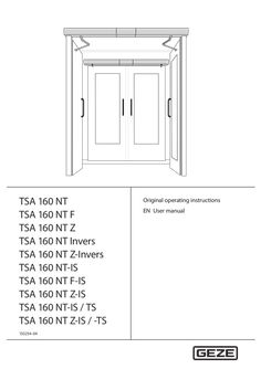
TSA 160 NT user manual
… operating instructions EN User manual TSA 160 NT Contents … For the user … Overview of the modes of operation … Operating elements … Door in normal operation … Operation … Selecting the mode of operation … Symbols and illustrations Warning notices Warning notices are used in these instructions to warn you of property damage and personal injury. XX Always read and observe these warning notices. XX Observe all measures marked with the warning symbol and warning word . Warning symbol Warning word Meaning Danger to persons. CAUTION Non-compliance can result in minor to medium injuries. Further symbols and illustrations Important information and technical notes are highlighted to explain correct operation. Symbol Meaning means “important note”; information about avoiding property damage means “additional Information” The user's attention should be drawn to important addition information. There is no danger to persons or property, but it is particularly useful to read the additional information carefully. XX … Symbol for an action: This means you have to do something. XX If there are several actions to be taken, keep to the given order. Product liability In compliance with the liability of the manufacturer for his products as defined in the German “Product Liability Act”, compliance with the information contained in this brochure (product information and intended use, misuse, product performance, product maintenance, obligations to provide information and instructions) must be ensured. Failure to comply releases the manufacturer from his statutory liability. … Special cases In certain cases, deviations from the information given in this user manual may occur. Examples: àà special wiring àà special function settings (parameters) àà special software XX Please contact the service technician responsible for further information. … More detailed information Information about commissioning and service can be found in the following documents: àà wiring diagram TSA 160 NT àà installation instructions TSA 160 NT … Explanation The side of the door where the hinges from which the door leaf is suspended are located. Usually that side of the door located in the opening direction. The side of the door facing the hinge side. Usually that side of the door located in the direction of closing movement. The active leaf of a double-leaf door. When the door is used, the active leaf must open as the first door leaf and close as the last door leaf. The secondary leaf of a double-leaf door. When the door is used, the passive leaf may not open until the active leaf has left the closing position and must close again as the first door leaf. Push button, switch or movement detector for activating the door drive. The activation device is located within the room enclosed by the door. Activation function in the modes of operation AUTOMATIC and EXIT ONLY 1). The activation device does not have any function in the NIGHT/OFF mode of operation. Push button, switch or movement detector for activating the door drive. The activation device is located outside the room enclosed by the door. Activation function in the AUTOMATIC mode of operation. The activation device does not have any function in the EXIT ONLY 1) and NIGHT/OFF modes of operation. Access control function (for example key switch or card reader) used by authorised persons to activate the door drive. The control function is active in the AUTOMATIC, EXIT ONLY1) and NIGHT/OFF modes of operation. Push button for opening and closing the door. Control function only in the AUTOMATIC and EXIT ONLY modes of operation1). The door is opened automatically when the button is first pressed and closed again automatically when the button is pressed the second time. The function can be activated during commissioning by parameter setting. When the door is pressed manually out of the closing position during an activated closing position inhibition, the door opens automatically as soon as a specific adjustable opening angle is exceeded. Presence detector (e.g. active infrared light switch) for protecting the swinging range of the door in the opening direction. As a rule the sensor is located on the hinge side of the door on the door leaf. Presence detector (for example active infrared light switch) for protecting the swinging range of the door in the closing direction. As a rule the sensor is located on the opposite hinge side of the door leaf. Self-locking switch with which immediate stopping of the door drive can be triggered in case of danger. The door drive remains in its current position until the user unlocks the stop switch again, thus terminating the stop situation. Electrical closing sequence control In normal operation of double-leaf door drives, the closing sequence of the door leaves is controlled by the control units of the door drives, with the passive leaf being closed first. The active leaf remains in the open position until the hold-open time of the passive leaf has expired. Only then does the active leaf begin to close. Integrated closing sequence control (-IS): In the event of a power failure for 2-leaf door systems, the closing sequence is controlled mechanically with TSA 160 NT-F-IS. The door leaves are closed by means of the power storage of the drives, with the active leaf being kept open by the integrated mechanical closing sequence control unit at approximately 30° opening angle before the closing position is reached. When the passive leaf has reached the closing position, it releases the active leaf by means of the mechanical elements of the integrated closing sequence control so that it can also close completely.. The EXIT ONLY mode of operation can only be selected with the optional mechanical programme switch. TSA 160 NT Introduction Term Explanation Electric strike Fail-secure electric strike Available as AC or DC electric strike version. When the door drive is activated, the electric strike is switched on by the control unit of the door drive provided the door is in the closing position. The electric strike remains activated until the door has left the closing position. Fail-safe electric strike DC electric strike version. The electric strike is switched off when the door drive is activated provided the door is in the closing position. The electric strike remains switched off until the door has left the closing position. The bar feedback function is a contact integrated in the door catch that is activated when the door is locked mechanically by the tie bolt of the door lock. It signals to the control unit that the door is locked mechanically and can therefore not be opened by the door drive. In this case the control unit ignores the control commands of all the activation devices. Push button for restarting the drive after the operating voltage has been switched on or after a fire alarm has been terminated. When the push button is pressed, the self-retention integrated in the drive is activated, causing the drive to be activated. When the door is closed in a de-energised state, the door leaf is impeded by the lock latch of the electric strike. To make sure the door can pass the lock latch safely during closing, an integrated limit switch is activated in the drive once a specific opening angle has been reached, reducing the braking strength. The door accelerates and closes into the lock at increased speed. In an energised state, this function is regulated by the drive control unit. Bar feedback Reset Latching function … For the user TSA 160 NT Carefully read and abide by this user manual before commissioning the door. Always observe the following safety instructions: àà Operating, maintenance and repair conditions specified by GEZE must be observed. àà The commissioning, mandatory installation, maintenance and repair work must be performed by experts authorised by GEZE. àà The connection to the mains voltage must be made by a professional electrician. àà No changes may be made to the system without prior agreement from GEZE. àà GEZE shall assume no liability for damage caused by unauthorised changes to the system. àà The owner is responsible for safe operation of the system. àà Have a service technician check the safe operation of the system at regular intervals. àà Should safety devices be misaligned, thus preventing them from fulfilling their intended purpose, further operation is not permissible. The service technician must be informed without delay. àà Make sure that the safety stickers are attached visibly to any glass leaves and are in a legible state. àà Protect the programme switch against unauthorised access. àà Danger of injury by sharp edges on the drive when removing the cover àà Danger of injury by parts hanging down àà This appliance can be used by children aged from … years and above and persons with reduced physical, sensory or mental capabilities or lack of experience and knowledge if they have been given supervision or instruction concerning use of the appliance in a safe way and understand the hazards involved. àà Children shall not play with the appliance. àà Cleaning and user maintenance shall not be made by children without supervision. … Set-up The door system shown is only a schematic diagram. For technical reasons, we cannot show all of the possibilities here. The operating elements can be arranged individually. Example: door drive TSA 160 NT, 1-leaf, transom installation … 10 *) Door drive Link arm or roller guide rail Smoke switch control unit *) Activation device outside (KA) (optional) Activation device authorised (KB) (optional) Smoke switch *) Activation device inside (KI) (optional) Programme switch (optional) Lockable mechanical program switch (MPS-ST) for releasing the programme switch Stop switch (optional) 11 12 13 14 15 16 17 18 19 20 CLOSE DOOR manual trigger switch *) Electric strike (on site) Door handle with door lock (on site) Inside building Outside building Closing safety sensor (SIS) (optional) Door transmission cable (optional) Opening safety sensor (SIO) (optional) Internal programme switch Reset switch (F-reset) (TSA 160 NT F only) optional, in connection with TSA 160 NT F … TSA 160 NT Overview of the modes of operation The following modes of operation can be set on the TSA 160 NT: àà Automatic mode àà Exit only àà Hold open àà Night mode àà OFF Mode of operation TPS* MPS/MPS-ST** DPS*** Key Automatic Explanatory notes Display aU àà Opening of … When the keys are pressed simultaneously, the mode of operation changes between 1-leaf opening and 2-leaf opening. On the DPS the LED operation. is lit in 1-leaf Exit only ls Door only opens and closes if someone exits. Only the inside activation devices are active. Hold open DO Door remains open. Night mode Na Door opens and closes only when activated using the key switch The inside and outside activation devices are inactive. Door is enabled and can be moved by hand. The inside and outside activation devices are inactive. OFF * ** *** … OFF OFF OFF Of Keypad programme switch (TPS) Mechanical programme switch (MPS)/mechanical programme switch with integrated key switch (MPS-ST) Display programme switch Operating elements The modes of operation can be set using the following operating elements: àà Internal programme switch on the door drive àà Keypad programme switch (optional) (see chapter … .1 Internal programme switch The following modes of operation can be set using the internal programme switch: àà Position II Automatic àà Position … Night/Off àà Position I Hold open. Special cases (e.g. special circuiting) may occur during the operation of the GEZE door drives. Behaviour may differ. If this is the case, please ask the service technician responsible. … .2 Description Keypad programme switch TPS (optional) àà Can be connected additionally to the internal programme switch (19). àà Setting of the mode of operation with the keypad programme switch is only possible when the internal programme switch is set to the … position. The system mode of operation is selected and the corresponding programme is displayed at the keypad programme switch. The keypad programme switch is accessible for everyone without a key switch. If desired, an additional key switch can be used for locking. Keypad programme switch TPS … .3 Mechanical programme switch MPS (optional) àà Can be connected additionally to the internal programme switch (19). At the mechanical programme switch MPS, the mode of operation for the system is selected and the corresponding programme is displayed. The mechanical programme switch is accessible for everyone without a key switch. Mechanical programme switch MPS With the mechanical programme switch MPS-ST, selection of the modes of operation is disabled if the key provided has been removed. Mechanical programme switch MPS-ST with integrated key switch … Door in normal operation In normal operation, the door is automatically opened and closed. What happens? An activation device (push button, switch or movement detector) is triggered Safety sensor close (SIS) is is triggered when the door is open (e.g. light sensor) Closing safety sensor (SIS) is triggered while the door is closing. Opening safety sensor (SIO) is triggered while door is opening. Opening safety sensor (SIO) is triggered when the door is closed. A person moves toward the opened door and a movement detector is triggered A person moves toward the closing door and a movement detector is triggered Door contacts an obstruction while opening Door contacts an obstruction while closing What does the door do? Door opens, waits the hold-open time and then closes again Door remains open Door reopens immediately The door stops and remains in position until the end of activation (door opens) or until the end of the holdopen time (door closes) Door remains closed Door remains open Door reopens immediately The door tries to open and closes after a motor running time (10s) + 10 sec. + hold-open time (depending on setting) The door presses closed with spring force Additional door functions Which switch/push button? Stop switch Activation device authorised (KB) (e.g. outside key switch) Activation device with radio board 10 What does the switch/push button do? The door stops immediately (in every mode of operation) and holds the position until the stop switch is unlocked Door opens once and closes after the hold-open time. The set mode of operation is retained. Door opens once and closes after the hold-open time. The set mode of operation is retained. TSA 160 NT Which switch/push button? Switch function Double push button Emergency lock … Operation What does the switch/push button do? The automated door can be activated using the switch function. Normal switch function: àà Switch contact opens the door and the door remains in the open position. àà Switch contact closes the door. Switch function with hold-open time: àà Switch contact opens the door. àà Switch contact closes the door or the door starts to close after the hold-open time. In the case of 2-leaf drives, a button with a double function can be connected via a configurable push button. This means that 1-leaf or 2-leaf opening is possible by pressing the push button. If the push button is pressed once, only the active leaf opens and closes after the hold-open time has expired. If the button is pressed twice within … s, both leaves open and close after the double leaf hold-open time has expired. When the emergency lock is used, a switch can close the 1- or 2-leaf system immediately. The doors close with the set force and without sensor sensors. There is an increased risk of injury. Operation The set parameters of the drive functions may only be modified by a service technician. The door parameters can be set or modified using the service menu. Querying and modifying of the set drive parameters are described in the wiring diagram. … Selecting the mode of operation … .1 Selecting the mode of operation at the mechanical programme switch Use the internal programme switch (19) to choose one of the three positions: àà Position II Automatic àà Position … Night/Off àà Position I Hold open. The required mode of operation is set. XX 11 Operation … .2 TSA 160 NT Selecting the mode of operation using the keypad programme switch XX Select the mode of operation required using the push buttons The LED of the current mode of operation lights up. and . Selecting mode of operation with additional key switch XX Activate the key switch briefly. The keypad programme switch is released, the required mode of operation can be selected. XX Activate the key switch briefly again. The keypad programme switch is blocked. … .3 Selecting the mode of operation at the mechanical programme switch MPS With the programme switch MPS XX Turn the rotary switch (21) to the required mode of operation. The mode of operation is set. 21 Mechanical programme switch MPS With the programme switch MPS-ST (key switch Operation of the mechanical programme switch MPS-ST is only possible with the supplied key (22). XX Insert the key (22) into the mechanical programme switch MPS-ST. XX Turn the key rotary switch (23) to the required mode of operation. The mode of operation is set. XX Remove the key. The mechanical programme switch MPS-ST locked. Mechanical programme switch MPS-ST with integrated key switch 12 TSA 160 NT … .4 Troubleshooting Selecting the mode of operation using the display programme switch Touch the required mode of operation on the display programme switch. The mode of operation is set and indicated on the display (24). XX 24 OFF Display programme switch Fault messages on the display If a fault occurs in the door system, it is displayed on the display programme switch about every 10 seconds. XX Read off the number of the fault message, note it down and notify the service technician. … Troubleshooting Problem Door opens and closes constantly Cause Remedy XX Clear the obstruction Obstruction in travel path Light beams or reflections, e.g. reflective XX Check detection area of movement detector floor, rain drops XX Check detection area of movement detectors, inform Misaligned movement detector service technician if necessary XX Clean the closing safety sensor Closing safety sensor (SIS) soiled XX Clean the opening safety sensor Opening safety sensor (SIO) soiled XX Remove obstruction and check door leaf for ease of Door only opens a crack Obstruction in travel path movement XX Remove obstruction and check door leaf for ease of Door does not open Obstruction in travel path movement Movement detector misaligned or de- XX Check the movement detector, notify a service techfective (outside) nician if necessary XX Unlock the stop Stop activated XX Select a different mode of operation “Night” mode of operation XX Select “Automatic” mode of operation “Exit only” mode of operation XX Unlock the door Door locked mechanically XX Notify a service technician Electric strike does not release XX Activate reset push button Fire alarm active (TSA 160 NT F only) XX Notify a service technician Drive defective XX Clean the closing safety sensor (SIS) Door does not close Closing safety sensor (SIS) soiled XX Notify a service technician Closing safety sensor (SIS) misaligned or defective XX Remove obstruction and check door leaf for ease of Obstruction in travel path movement XX Check the movement detector, notify a service techMovement detector operates uninterruptedly nician if necessary XX Select a different mode of operation “Hold open” mode of operation Current impulse push button function XX Terminate activation by pressing the push button controls again XX Activate key switch for release Display programme switch Display programme switch is disabled cannot be operated XX Notify a service technician Display programme switch defective 13 Cleaning and maintenance TSA 160 NT Problem Cause Display programme switch Connection between display prodisplays … 7) Wipe with damp cloth. Do not use a cleaning agent.. Maintenance The owner must ensure that the system is working perfectly. To guarantee perfect operation, the door system must be serviced regularly by a service technician. Maintenance must be carried out at least once a year or according to the maintenance display on the display programme switch. Installation, maintenance and repair work must be performed by experts authorised by GEZE. If a dot appears in the bottom right-hand part of the display, maintenance is due. XX Notify a service technician. The maintenance display lights up after the specified calendar period or number of opening cycles, depending on what occurs first: GEZE offers maintenance contracts with the following services: àà Inspection of fixing elements for firm fit àà Performance of miscellaneous adjustment work àà Performance of operational checks àà Checking all the safety and control equipment of the door system àà Lubrication of all the moveable parts 14 TSA 160 NT … ) Section 6, power-operated doors must be inspected for safety by an expert before initial commissioning and at least once a year. GEZE offers the following services: Inspection and operational checks of all safety and control equipment in compliance with the requirements in the test log for power-operated windows, doors and gates; Sliding doors and sliding gates ZH 1/
PDF | 411 KB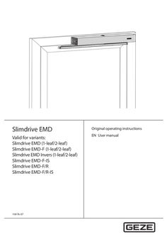
Slimdrive EMD EMD-F EMD-F-IS EMD-F/R EMD Invers
… operating instructions EN User manual Slimdrive EMD/EMD-F Contents … Overview of the modes of operation … Operating elements … 10 Door in normal operation … Operation … .4 Selecting the mode of operation … 12 Selecting the mode of operation at the mechanical programme switch … 12 Selecting the mode of operation at the mechanical programme switch MPS … 12 Selecting the mode of operation using the display programme switch … 13 Selecting the mode of operation using the keypad programme switch … Symbols and illustrations Warning notices In these instructions, warning notices are used to warn against material damage and injuries. XX Always read and observe these warning notices. XX Observe all measures marked with the warning symbol and warning word. Warning symbol Warning word CAUTION Meaning Danger to persons. Non-compliance can result in minor injuries. More symbols and illustrations Important information and technical notes are highlighted to explain correct operation. Symbol Meaning means “important note”; Information on avoiding material damage, improved understanding or optimising the workflows means “additional Information”; The user's attention should be drawn to important addition information. There is no danger to persons or property, but it is particularly useful to read the additional information carefully XX … Symbol for an action: This means you have to do something. XX If there are several actions to be taken, keep to the given order. Product liability In compliance with the liability of the manufacturer for his products as defined in the German “Product Liability Act”, compliance with the information contained in this brochure (product information and intended use, misuse, product performance, product maintenance, obligations to provide information and instructions) must be ensured. Failure to comply releases the manufacturer from his statutory liability. … Special cases In certain cases, such as with àà Special wiring àà special function settings (parameters) àà Special software differences from the information given in this user manual may occur. XX If this is the case, please ask the service technician responsible. … More detailed information Information about commissioning and service can be found on the following diagrams: àà Wiring diagram Slimdrive EMD àà Installation instructions Slimdrive EMD … Slimdrive EMD/EMD-F Terms Term Hinge side Explanation The side of the door where the hinges from which the door leaf is suspended are located. Usually that side of the door located in the opening direction. Opposite hinge side The side of the door facing the hinge side. Usually that side of the door located in the direction of closing movement. Active leaf The active leaf of a double leaf door. When the door is used, the active leaf must open as the first door leaf and close as the last door leaf. Passive leaf The secondary leaf of a double leaf door. When the door is used, the passive leaf may not open until the active leaf has left the closing position and must close again as the first door leaf. Activation device inside (KI) Push button, switch or movement detector for activating the drive unit. The activation device is located within the room enclosed by the door. Activation function in the AUTOMATIC and EXIT ONLY modes of operation. The activation device does not have any function in the NIGHT/OFF mode of operation. Activation device outside (KA) Push button, switch or movement detector for activating the drive unit. The activation device is located outside the room enclosed by the door. Activation function in the AUTOMATIC mode of operation. The activation device does not have any function in the EXIT ONLY and NIGHT/OFF modes of operation. Activation device Access control function (for example key switch or card reader) used by authorised authorised (KB) persons to activate the drive unit. The activation function is active in the AUTOMATIC, EXIT ONLY and NIGHT/OFF modes of operation. Activation device with current Push button for opening and closing the door. Activation function only in the AUTOimpulse function MATIC and EXIT ONLY modes of operation. The door is opened automatically when the button is first pressed and closed again automatically when the button is pressed the second time. The function can be activated during commissioning by parameter setting using the display programme switch, ST 220 or GEZEconnects. If the activation device is connected to the passive leaf control unit by means of the “current impulse” function, both door leaves open when activated, even when the passive leaf control system is deactivated. Push&Go When the door is pressed manually out of the closing position with an activated Push & Go function in the AUTOMATIC mode of operation, the door opens automatically as soon as a specific adjustable opening angle is exceeded. Opening safety sensor (SIO) Presence detector (e.g. active infrared light sensor) for protecting the swivelling range of the door in the opening direction. As a rule the sensor is located on the hinge side of the door on the door leaf. Closing safety sensor (SIS) Presence detector (for example active infrared light sensor) for protecting the swivelling range of the door in the closing direction. As a rule the sensor is located on the opposite hinge side of the door leaf. Emergency stop button Self-locking switch with which immediate stopping of the drive unit can be triggered in case of danger. The drive unit remains in its current position until the user unlocks the emergency stop switch again, thus terminating the emergency stop situation. Low-energy function The Slimdrive EMD can be used as a low-energy drive. In low-energy function the force needed for opening and closing the door is reduced to 67 N and the opening and closing time is reduced. This lowers the danger of a person bumping into the moving leaf. If people who are particularly vulnerable pass through the door, special measures must be taken to eliminate the contact hazard (e.g. use of open/closing safety sensors). … Slimdrive EMD/EMD-F Term Closing sequence control Electric strike Bolt feedback Reset Latching function Door closer mode Servo operation Introduction Explanation Electrical closing sequence control In normal operation of double leaf drive units, the closing sequence of the door leaves is controlled by the control units of the drive units, with the passive leaf being closed first. The active leaf remains in the open position until the passive leaf has reached the closed position, then the active leaf begins to close. Integrated closing sequence control (-IS) In the event of a power failure, the closing sequence is controlled mechanically on double leaf door systems with Slimdrive EMD-F-IS. The door leaves are closed by means of the power storage device of the drives, with the active leaf being kept open by the integrated mechanical closing sequence control. When the passive leaf has reached the closing position, it releases the active leaf by means of the mechanical elements of the integrated closing sequence control so that it can also close completely. Fail-secure electric strike Available as AC or DC electric strike version. When the drive unit is activated, the electric strike is switched on by the control unit of the drive unit provided the door is in the closing position. The electric strike remains activated until the door has left the closing position. Fail-safe electric strike DC electric strike version. The electric strike is switched off when the drive unit is activated provided the door is in the closing position. The electric strike remains switched off until the door has left the closing position. The bolt feedback function is a contact integrated in the lock latch that is activated when the door is locked mechanically by the tie bolt of the door lock. It signals to the control unit that the door is locked mechanically and can therefore not be opened by the drive unit. In this case the control unit ignores the control commands of all the activation devices. Push button for restarting the drive after the operating voltage has been switched on or after a fire alarm has been terminated. When the push button is pressed, the latching integrated in the drive is activated, causing the drive to be switched on. When the door is closed in a de-energised state, the door leaf is impeded by the lock latch of the electric strike. To make sure the door can pass the lock latch safely during closing, an integrated limit switch is activated in the drive once a specific opening angle has been reached, reducing the braking strength. The door accelerates and closes into the lock at increased speed. In an energised state, this function is regulated by the drive control unit. In automatic mode (normal operation) the automatic swing door drive can behave like a door closer. This means that closing is torque-controlled. This closing torque can be adjusted and adapted to the respective passage situation. If servo operation is used, the swing door drive supports manual opening through moment of force. The support torque and the support period can be set for this support. … Slimdrive EMD/EMD-F Fundamental safety precautions For the user Carefully read and abide by this user manual before commissioning the door. Always observe the following safety instructions: àà Operating, maintenance and repair conditions specified by GEZE must be observed. àà The commissioning, mandatory installation, maintenance and repair work must be performed by experts authorised by GEZE. àà The connection to the mains voltage must be made by a professional electrician. àà No changes may be made to the system without prior agreement from GEZE. àà GEZE shall assume no liability for damage caused by unauthorised changes to the system. àà The owner is responsible for safe operation of the system. àà Have a service technician check the safe operation of the system at regular intervals. àà Should safety devices be misaligned, thus preventing them from fulfilling their intended purpose, further operation is not permissible. The service technician must be informed without delay. àà Make sure that the safety stickers are attached visibly to any glass leaves and are in a legible state. àà Protect the programme switch against unauthorised access. àà Danger of injury by sharp edges on the drive when removing the weather hood àà Danger of injury by parts hanging down àà This appliance can be used by children aged from … years and above and persons with reduced physical, sensory or mental capabilities or lack of experience and knowledge if they have been given supervision or instruction concerning use of the appliance in a safe way and understand the hazards involved. àà Children shall not play with the appliance. àà Cleaning and user maintenance shall not be made by children without supervision. For the service technician àà GEZE does not accept any warranty for combinations with third-party products. àà Only combine third-party products with original parts following agreement by GEZE. Furthermore, only original GEZE parts may be used for repair and maintenance work. àà The power connection and protective earth conductor test must be carried out in accordance DIN VDE 0100-610. àà Use an on-site automatic cut-out as the line-side disconnecting device, the dimensioning of which is matched to the type, cross-section, type of routing and ambient conditions of the on-site power supply circuit. The automatic cut-out must have at least … Structure The door system shown is only a schematic diagram. For technical reasons, we cannot show all of the possibilities here. The operating elements can be arranged individually. Example: Drive unit Slimdrive EMD-F, 1-leaf, transom installation … 10 Drive unit Link arm or lever Smoke switch control unit 1) Outside contact sensor (KA) Mechanical contact (KB) Smoke switch 1) Contact sensor inside (KI) Display programme switch Key switch for enabling the display programme switch Emergency stop switch (optional) (optional) (optional) (optional) (optional) (optional) 11 12 13 14 15 16 17 18 19 20 Manual trigger switch “CLOSE DOOR” 1) Electric strike Door handle with door lock inside outside Closing safety sensor (SIS) Door transmission cable Opening safety sensor (SIO) Reset button Internal programme switch (optional) (on site) (optional) (optional) (optional) 1) optional, in conjunction with Slimdrive EMD-F … Slimdrive EMD/EMD-F Overview of the modes of operation The following modes of operation can be set on the Slimdrive EMD: àà Automatic àà Exit only àà Hold open àà Night mode àà OFF Mode of operation MPS/MPS-ST/ TPS* DPS** Key Automatic Explanatory notes Display aU àà Opening of … . When the keys are pressed simultaneously, the mode of operation changes between 1-leaf opening and 2-leaf opening. On the DPS the LED is lit in 1-leaf operation. Exit only ls Door only opens and closes if someone exits. Only the inside activation devices are active. Hold open DO Door remains open. Night mode Na Door opens and closes only when activated using the key switch The inside and outside activation devices are inactive. Door is enabled and can be moved by hand. The inside and outside activation devices are inactive. OFF * ** … OFF OFF Of Mechanical programme switch MPS/mechanical programme switch with integrated key switch MPS-ST/keypad programme switch TPS Display programme switch Operating elements The modes of operation can be set using the following operating elements: àà Internal programme switch (20) on the drive unit (see chapter … .1 Internal programme switch The mode of operation on the drive unit can be selected using the internal programme switch (20). The switch position indicates the current mode of operation: aU àà Setting II Automatic Na àà Setting … .2 Description Mechanical programme switch MPS (optional) àà Can be connected additionally to the internal programme switch (20). At the mechanical programme switch MPS, the mode of operation for the system is selected and the corresponding programme is displayed. The mechanical programme switch is accessible for everyone without a key switch. Mechanical programme switch MPS With the mechanical programme switch MPS-ST, selection of the modes of operation is disabled if the key provided has been removed. Mechanical programme switch MPS-ST with integrated key switch … .3 Display programme switch DPS (option) àà Can be connected additionally to the internal programme switch (20). If a dot appears on the bottom right-hand part of the display, maintenance is due. If a dot appears in the middle of the display, the door has not yet been fully initialised after the mains voltage has been switched on. Initialisation is carried out automatically when the drive opens and closes the door. As an option, operation of the display programme switch can be restricted by a key switch SCT. OFF Display programme switch DPS … .4 Slimdrive EMD/EMD-F Keypad programme switch TPS (optional) àà Can be connected additionally to the internal programme switch (20). àà Setting of the mode of operation using the keypad programme switch is only possible when the internal programme switch (20) is set to the … position. The system operating status is selected and the corresponding programme is displayed at the keypad programme switch. The keypad programme switch is accessible for everyone without a key switch. If desired, an additional key switch can be used for blocking. Keypad programme switch TPS … Door in normal operation In normal operation, the door is automatically opened and closed. What happens? An activation device (push button, switch or movement detector) is triggered. Closing safety sensor (SIS) is triggered when the door is open (e.g. light switch). Closing safety sensor (SIS) is triggered while the door is closing. Opening safety sensor (SIO) is triggered while door is opening. Opening safety sensor (SIO) is triggered when the door is closed. A person moves toward the opened door and a movement detector is activated. A person moves toward the closing door and a movement detector is activated. Door contacts an obstruction when opening. The opening safety sensor has not been activated. Door contacts an obstruction when closing. The closing safety sensor has not been activated. 10 What does the door do? Door opens, waits the hold-open time and then closes. Door remains open. The door immediately opens again or stops depending on the parameter setting. The door stops and remains in position until the end of activation (door opens) or until the end of the hold-open time (door closes). Door remains closed. Door remains open. Door reopens immediately. Door stops, waits and attempts again to move to the open position at a reduced speed. Then the door closes again. Door reopens immediately, waits the hold-open time and then closes at a reduced speed. When door closer mode is used with the closing safety sensor deactivated, the drive presses against the obstacle with the force set. Slimdrive EMD/EMD-F Description Additional door functions Which switch/push button? Emergency stop switch What does the switch/push button do? The door stops immediately (in every mode of operation) and holds the position until the emergency stop switch is unlocked. Key switch of the display programme switch If a key switch is connected to the display programme switch, the operation of the display programme switch can be locked or released with it. Activation device authorised (KB) (e.g. outside key switch) Door opens once and closes after the hold-open time. The set mode of operation is retained. Switch function The automated door can be activated using the switch function. Normal switch function: àà Switch contact opens the door and the door remains in the open position. àà Switch contact closes the door. Switch function with hold-open time: àà Switch contact opens the door. àà Switch contact closes the door or the door starts to close after the hold-open time. Double push button In the case of 2-leaf drives, a button with a double function can be connected via a push button for which parameters can be set. This means that 1-leaf or 2-leaf opening is possible by pressing the push button. If the push button is pressed once, only the active leaf opens and closes after the hold-open time has expired. If the button is pressed twice within … s, both leaves open and close after the double leaf hold-open time has expired. Emergency lock When the emergency lock is used, a switch can close the 1- or 2-leaf system immediately. The doors close with the set force and without safety sensors and obstacle detection. There is an increased risk of injury. WC control The door opens after the elbow switch on the outside of the toilet has been pressed, and closes automatically after the set hold-open time has passed. When the push button is activated inside the toilet cabin, the system is switched to the exit only mode of operation, which means the outer push button no longer opens the door. At the same time, the lights indicate that the toilet is occupied. The electric strike is supplied with current, preventing manual opening of the door from outside. Activating the “inner” push button again or through manual opening from inside, the WC function (exit only mode of operation) is cancelled and the drive switched back to the automatic mode of operation. The ‘occupied’ displays and lights go out. 11 Operation … Slimdrive EMD/EMD-F Operation The set parameters of the drive functions may only be modified by a service technician. … Selecting the mode of operation … .1 Selecting the mode of operation at the mechanical programme switch àà The internal programme switch (20) can be deactivated by a service technician. àà In the … programme switch setting the mode of operation can be changed using a connected display programme switch (optional). àà In the programme settings I and II the display programme switch (optional) is used to display the mode of operation set and to output fault messages. XX Set the internal programme switch (20) to the required position (II, … .2 Selecting the mode of operation at the mechanical programme switch MPS àà Setting of the mode of operation using the mechanical programme switch is only possible when the internal programme switch (20) is set to the … position. With the programme switch MPS XX Turn the rotary switch (21) to the required mode of operation. The mode of operation is set. 21 Mechanical programme switch MPS 12 Slimdrive EMD/EMD-F Operation With the programme switch MPS-ST (key switch) Operation of the mechanical programme switch MPS-ST is only possible with the supplied key (22). XX Insert the key (22) into the mechanical programme switch MPS-ST. XX Turn the key rotary switch (23) to the required mode of operation. The mode of operation is set. XX Remove the key. The mechanical programme switch MPS-ST locked. Mechanical programme switch MPS-ST with integrated key switch … .3 Selecting the mode of operation using the display programme switch àà Setting of the mode of operation using the display programme switch is only possible when the internal programme switch (20) is set to the … position. Touch the required mode of operation on the display programme switch. The mode of operation is set and indicated on the display (24). XX 24 OFF Display programme switch DPS Enabling operation of the display programme switch with key switch SCT (optional) XX Press key switch SCT briefly. Operation of the display programme switch is enabled. XX Press key switch SCT briefly again. Operation of the display programme switch is disabled. Fault messages on the display If a fault occurs in the door system, it is displayed on the display programme switch about every … seconds. XX Read off the number of the fault message, note it down and notify the service technician. 13 Operation … .4 Slimdrive EMD/EMD-F Selecting the mode of operation using the keypad programme switch àà Setting of the mode of operation using the keypad programme switch is only possible when the internal programme switch (20) is set to the … position. The desired operating status is selected by pressing the and keys. The LED of the current operating state lights up. XX When using a key switch: XX Enable by operating the key switch once briefly. Disable the operation of the keypad programme switch: XX Activate the key switch briefly again. Keypad programme switch TPS Fault messages in the keypad programme switch If a fault occurs in the system, this is indicated by at least … LEDs lighting up alternately with the current operating status. XX Read off the light combination, note this down and inform a service technician. 14 Slimdrive EMD/EMD-F … Troubleshooting Troubleshooting Problem Door only opens and closes slowly Cause Obstruction in travel path Closing safety sensor (SIS) soiled Door opens and closes constantly Closing safety sensor (SIS) misaligned or defective Obstruction in travel path Irradiation or reflections, e.g. reflective floor, falling rain Misaligned movement detector Remedy XX Remove obstruction and check door leaf for ease of movement XX Have the door close completely once; door moves after obstruction at a safe speed until the complete closing procedure has been completed XX Clean the closing safety sensor XX Have the door close completely once; door moves after obstruction at a safe speed until the complete closing procedure has been completed XX Notify a service technician XX XX XX Door only opens a crack Obstruction in travel path XX Door does not open Obstruction in travel path XX Movement detector misaligned or defective (outside) Emergency stop button activated “Night” mode of operation “Exit only” mode of operation Door locked mechanically Electric strike does not release Fire alarm active (Slimdrive EMD-F only) Drive defective Closing safety sensor (SIS) soiled Closing safety sensor (SIS) misaligned or defective Obstruction in travel path XX Movement detector triggers constantly XX “Hold open” mode of operation Current impulse push button function controls Display programme switch is disabled Display programme switch defective Keypad programme switch is disabled Keypad programme switch is faulty Connection between display programme switch and control unit faulty Display programme switch or control unit defective Power failure Connection between display programme switch and control unit faulty Display programme switch or control unit defective XX Door does not close (After … minutes of continuous activation by the safety sensor, the Slimdrive EMD/ Slimdrive EMD-F automatically closes the door in low-energy mode) Display programme switch cannot be operated Keypad programme switch cannot be operated Display programme switch displays … 8 Display programme switch without display XX XX XX XX XX XX XX XX XX Clear the obstruction Check detection area of movement detector Check detection area of movement detector Remove obstruction and check door leaf for ease of movement Remove obstruction and check door leaf for ease of movement Check the movement detector, notify a service technician if necessary Unlock emergency stop button Select a different mode of operation Select “Automatic” mode of operation Unlock the door Notify a service technician Activate reset button (19) Notify a service technician Clean the closing safety sensor (SIS) Notify a service technician XX Remove obstruction and check door leaf for ease of movement Check the movement detector, notify a service technician if necessary Select a different mode of operation Terminate activation by pressing the push button again Activate key switch for release Notify a service technician Activate key switch for release Notify a service technician Notify a service technician XX Notify a service technician XX XX Check mains fuse Notify a service technician XX Notify a service technician XX XX XX XX XX XX 15 Troubleshooting Problem Keypad programme switch without display Display of fault messages on the display programme switch Slimdrive EMD/EMD-F Cause Power failure Connection between keypad programme switch and control unit faulty Keypad programme switch or control unit defective Fault in the door system Remedy XX Check mains fuse XX Notify a service technician XX Notify a service technician XX Note fault messages. Up to 10 different fault messages can occur in succession. The display changes about every 10 seconds. Notify a service technician Note the LED combination. Notify a service technician. XX Display of fault messages Fault in the door system on the keypad programme switch 16 XX XX Slimdrive EMD/EMD-F … Cleaning Cleaning and maintenance Caution! Danger of injury due to impact and crushing! XX Set the mode of operation to OFF. XX Secure door leaves against accidental movement before carrying out cleaning work. What is to be cleaned? Closing safety sensor (SIS) (e.g. light switch) Glass surfaces Stainless surfaces Coated surfaces Anodised surfaces Display programme switch, keypad programme switch, mechanical programme switch … 7) XX Wipe with soft cloth. Do not use a cleaning agent Maintenance The owner must ensure that the system is working perfectly. To guarantee perfect operation, the door system must be serviced regularly by a service technician. Maintenance must be carried out at least once a year or according to the maintenance display on the display programme switch. Installation, maintenance and repair work must be performed by experts authorised by GEZE. If a dot appears on the bottom right-hand part of the display, maintenance is due. XX Notify a service technician. The maintenance display lights up after the specified calendar period or number of opening cycles, depending on what occurs first: … year or 500,000 cycles GEZE offers maintenance contracts with the following services: àà Check fastening elements for a firm fit àà Performance of miscellaneous adjustment work àà Performance of operational checks àà Check all the safety and control equipment of the door system àà Lubricate all moving parts … ) Section 6, power-operated doors must be inspected for safety by an expert before initial commissioning and at least once a year. GEZE offers the following services: Inspection and operational checks of all safety and control equipment in compliance with the requirements in the test log for power-operated windows, doors and gates; Sliding doors and sliding gates ZH 1/
PDF | 429 KB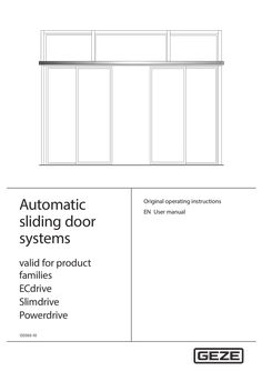
User manual Automatic sliding doors
… operating instructions EN User manual DCU1-NT, DCU1-2M-NT, DCU1, DCU1-2M Contents … For the user … Overview of the modes of operation … Operating elements … 10 Door in normal operation … Operation … Selecting the mode of operation … 13 Blocking and releasing modes of operation … Symbols and illustrations Warning notices Warning notices are used in these instructions to warn you of personal injury and property damage. XX Always read and observe these warning notices. XX Observe all the measures that are marked with the warning symbol and warning word . Warning symbol Warning word Meaning WARNING Danger to persons. Non-compliance may result in death or serious injuries. CAUTION Danger to persons. Non-compliance can result in minor to medium injuries. Further symbols and illustrations Important information and technical notes are highlighted to explain correct operation. Symbol Meaning means “important note”; information about avoiding property damage means “additional Information” The user's attention should be drawn to important addition information. There is no danger to persons or property, but it is particularly useful to read the additional information carefully. XX Symbol for an action: This means you have to do something. XX If there are several actions to be taken, keep to the given order. Escape and rescue route; means the sliding door cannot be operated in escape and rescue routes Not an escape and rescue route; means the sliding door cannot be operated in escape and rescue routes BO … BO Break-out; means BOthat the door leaves and side panels are equipped with a break-out function BO No break-out; means the function is not possible for break-out doors Product liability In accordance with the manufacturer's liability for their products as defined in the German “Produkthaftungsgesetz” (Product Liability Act), the information contained in this user manual (product information and proper use, misuse, product performance, product maintenance, obligations to provide information and instructions) is to be noted and followed. Failure to comply releases the manufacturer from his statutory liability. … Special cases In certain cases, deviations from the information given in this user manual may occur. Examples: àà Special wiring àà Special function settings (parameters) àà Special software XX Please contact the service technician responsible for further information. … DCU1-NT, DCU1-2M-NT, DCU1, DCU1-2M More detailed information Information for commissioning and maintenance can be found in the wiring diagram and in the installation instructions for the various automatic sliding doors. … Terms Term Activation device inside (KI) Explanation Push button, switch or movement detector for activating the door drive. The activation device is located within the room enclosed by the door. Activation function in the “Automatic” and “Exit only” modes of operation. The activation device does not have any function in the “Night/Locked” and “Off” mode of operation. Activation device outside (KA) Push button, switch or movement detector for activating the door drive. The activation device is located outside the room enclosed by the door. Activation function in the “Automatic” mode of operation. The activation device does not have any function in the “Exit only”, “Night/Locked” and “Off” mode of operation. Activation device authorised Access control function (for example key switch or card reader) used by authorised (KB) persons to activate the door drive. The activation function is active in the “Automatic” “Exit only”, “Night/Locked” and “Off” modes of operation. Opening safety sensor (SIO) Presence detector (e.g. active infrared light sensor) for protecting the swinging range of the door in the opening direction. The sensor secures the secondary closing edge. Closing safety sensor (SIS) Presence detector (e.g. active infrared light sensor) for protecting the swinging range of the door in the closing direction. The sensor secures the main closing edge on the inside and outside. Emergency stop Self-locking switch with which immediate stopping of the door drive can be triggered in case of danger. The door drive remains in its current position until the user releases the emergency stop switch again, thus terminating the emergency stop situation. Emergency lock When the emergency lock is triggered, the door is closed and locked. The activations and safety devices are deactivated during the closing process. Reset Push button for restarting the drive after the operating voltage has been switched on or after a fire alarm has been terminated. When the push button is pressed, the self-retention integrated in the drive is activated, causing the drive to be activated. … For the user Fundamental safety precautions Carefully read and abide by this user manual before commissioning the door. Always observe the following safety instructions: àà Operating, maintenance and repair conditions specified by GEZE must be observed. àà The commissioning, mandatory installation, maintenance and repair work must be performed by experts authorised by GEZE. àà Any relevant additional country-specific and European directives must also be observed. àà Use in dry rooms only. àà The intervals for safety-related testing are to be complied with based on the country-specific regulations. àà The connection to the mains voltage must be made by a professional electrician. àà No changes may be made to the system without prior agreement from GEZE. àà GEZE shall assume no liability for damage caused by unauthorised changes to the system. àà The owner is responsible for safe operation of the system. àà Have a service technician check the safe operation of the system at regular intervals. àà Should safety devices be misaligned, thus preventing them from fulfilling their intended purpose, further operation is not permissible. The service technician must be informed without delay. àà Make sure that the safety stickers are attached visibly to any glass leaves and are in a legible state. àà Protect the programme switch against unauthorised access. àà Danger of injury by sharp edges on the drive when removing the cover àà Danger of injury by parts hanging down àà This appliance can be used by children aged from … years and above and persons with reduced physical, sensory or mental capabilities or lack of experience and knowledge if they have been given supervision or instruction concerning use of the appliance in a safe way and understand the hazards involved. àà Children shall not play with the appliance. àà Cleaning and user maintenance shall not be made by children without supervision. … .1 Automatic door systems àà The sliding door system is used for the automatic opening and closing of a building passage. àà The sliding door system may only be used in a vertical installation position and in dry rooms within the permitted application area. àà The sliding door system is designed for pedestrian traffic in buildings. àà The sliding door system is not designed for the following uses: àà for industrial use àà for areas of application which do not serve pedestrian traffic (such as garage doors) àà on mobile objects such as ships àà The sliding door system may only be used: àà in the modes of operation provided for by GEZE àà with the components approved / released by GEZE àà with the software delivered by GEZE àà in the installation variants / types of installation documented by GEZE àà within the tested/approved area of application (climate / temperature / IP rating) àà Any other use is considered non-intended and will lead to the exclusion of all liability and warranty claims to GEZE. àà The automatic sliding door system Slimdrive SL-T30 is intended for use in fire protections closer. àà The automatic sliding door system Slimdrive SL-RD is intended for use at smoke protection doors. àà The automatic sliding door systems Slimdrive SL RC2 and Slimdrive SC RC2 are intended for use as burglary-resistant sliding doors with Resistance class 2. àà Only automatic FR and BO (Break-Out) sliding door systems are intended for use in escape and rescue routes. … Fundamental safety precautions DCU1-NT, DCU1-2M-NT, DCU1, DCU1-2M Important information about doors in escape and rescue routes (FR drives, break-out drives) àà Do not place objects in the passage area. àà Existing protective door leaves/safety leaves on sliding doors must be closed again after cleaning. àà The programme switch for changing the mode of operation on automatic door drives must be secured against activation by unauthorised persons. àà When using a key operated programme switch, the key must be removed after changing the mode of operation. àà The door may only be locked by authorised persons. … .2 FR drives The automatic FR sliding doors are equipped with components which allow them to be used as escape and rescue doors. Redundant drive design (2 motors) If the power supply fails (e.g. power failure), the sliding doors are opened with a battery (not in the “Night/ Locked” mode of operation). Switching over to safe mode If a fault which could impede the automatic opening of the sliding door is detected in the drive, the door leaves are opened. Deactivation of the escape and rescue route function àà By switching to the “Night/Locked” mode of operation, the sliding door is no longer available as an escape and rescue route. àà The “Night/Locked” mode of operation is not a defined mode of operation according to the guidelines on automatic sliding doors in escape and rescue routes (AutSchR). àà Only authorised persons may change the mode of operation with the key push button at the programme switch following authorisation (for example via the key switch). àà Switching to “Night/Locked” may only occur if the emergency exit route is no longer used, i.e. people are no longer in the building or an escape and rescue chart indicates other emergency exit routes for this time period. Reduced opening width To teach-in a reduced opening size, the operator must submit the escape route width specified for the escape route in writing. Only when this document has been submitted is it permitted to teach-in a reduced opening width. The set reduced opening width must be at least as large as the required escape path width. A copy of the document must be included with the service or test log. The reduced opening width may not be less than 30 % of the full opening width. The control cannot learn a smaller reduced position. Product version FR-DUO Two emergency exit directions possible. Product version FR-LL The door is locked in the “Shop closing time” mode of operation so that opening from the outside is prevented. Product version FR-RWS (RWS = emergency exit system) Additional mode of operation – similar to “Night/Locked”, but with a lock that ensures a fail-safe escape route function. Opening is enabled by means of a required emergency stop switch. … .3 Break-out drives The door leaves and side panels can be broken out in the “Automatic”, “Hold open” and “Shop closing time” modes of operation in the direction of emergency exit. … .4 RC2 drives The burglar-resistant function RC2 is only enabled in the “Night/Locked” mode of operation. When the door is operated in “Night/Locked” mode of operation, the rescue route function is deactivated. … Set-up Description The door system shown is only a schematic diagram. For technical reasons, we cannot show all of the possibilities here. The operating elements can be arranged individually. … DCU1-NT, DCU1-2M-NT, DCU1, DCU1-2M Overview of the modes of operation The following modes of operation can be set on the automatic sliding doors: àà Automatic àà Exit only àà Hold open àà Night/Locked àà Off … .1 Settings on the display programme switch (DPS) Mode of operation Key Automatic àà Full opening width Display DE EN FR IT Explanation aU aU aU aU ls eO sU sU D O hI op pa No NO NI N- Na NI NO NI of of of + àà Reduced opening width * + Exit only (one-way operation) Hold open (not for SL RD) Night/Locked (For FR-RWS, see special function below) Off (service/cleaning position) * of Door opens and closes again. Inside and outside activation devices active. Door opens the complete opening width. LED is off. Door opens only part of the possible opening width (can be set). LED lights up. Activation device internal active. Outer activation device only active as long as door is not closed. Door only opens for passage from the inside to the outside. The full/reduced opening width can be set as described under the “Automatic” mode of operation. Door remains open. The full/reduced opening width can be set as described under the “Automatic” mode of operation. Displayed until door is closed and locked (if lock is present). Door is closed and locked (if lock is present). Only “authorised” activation device is active. The drive is switched off for maintenance purposes. FR door moves to the open position. The door leaves can be moved freely by hand. Activation and safety sensors are without function. Drive motor and locking are switched off. Observe notes in Chapter … .2 Special functions for FR-RWS Mode of operation Key RWS Night/Locked … .2 2× Display DE EN FR IT Explanation N® N® N® N® No M O M I N- Na NI NO NI The door is locked by the motor brake. Opening is enabled by means of the emergency stop switch. Displayed until door is closed and locked (if lock is present). Door is closed and locked (if lock is present). Opening is enabled by means of the emergency stop switch. Settings on keypad programme switch (TPS) Mode of operation Automatic Key Display or m Explanation Door opens and closes again. Inside and outside activation devices active. m m l m àà Full opening width … + Door opens the complete opening width. DCU1-NT, DCU1-2M-NT, DCU1, DCU1-2M Mode of operation àà Reduced opening width * Key Exit only (one-way operation) Description Display + m or m l Explanation Door opens only part of the possible opening width (can be set). Activation device internal active. Outer activation device only active as long as door is not closed. Door only opens for passage from the inside to the outside. The full/reduced opening width can be set as described under the “Automatic” mode of operation. m m Hold open (not for SL-RD) m or m Door remains open. The full/reduced opening width can be set as described under the “Automatic” mode of operation. m m l Night/Locked m or l Door is closed and locked (if lock is present). Movement detector not active. Only “authorised” activation device is active. m m m Off (service/cleaning position) l m m The drive is switched off for maintenance purposes. FR door moves to the open position. The door leaves can be moved freely by hand. Activation and safety sensors are without function. Drive motor and locking are switched off. m m * Observe notes in Chapter … .3 Settings on the mechanical programme switch MPS/MPS-ST Not for emergency exit system. Mode of operation Automatic Setting àà Full opening width Explanation Door opens and closes again. Inside and outside activation devices active. Door opens the complete opening width. àà Reduced opening width * Door opens only part of the possible opening width (can be set). Exit only (one-way operation) Activation device internal active. Outer activation device only active as long as door is not closed. Door only opens for passage from the inside to the outside. The full/reduced opening width can be set as described under the “Automatic” mode of operation. Door remains open. Hold open Night/Locked Off (service/cleaning position) * Door is closed and locked (if lock is present). Movement detector not active. Only “authorised” activation device is active. The drive is switched off for maintenance purposes. The door leaves can be moved freely by hand. Activation and safety sensors are without function. Drive motor and locking are switched off. FR door moves to the open position. Observe notes in Chapter … DCU1-NT, DCU1-2M-NT, DCU1, DCU1-2M Operating elements The modes of operation can be set using the following operating elements: àà Display programme switch DPS (see Chapter … .1 Display programme switch (DPS) The modes of operation can be set at the display programme switch by pressing the respective keys. Operation by unauthorised persons can be blocked as follows: àà Connection of an additional key switch or àà Assignment of a password, which the service technician sets with the ST220 in the service menu If a dot appears on the bottom right-hand part of the display, maintenance is due. OFF If a dot appears on the left part of the display, the leaf position is unknown. This can be the case, for example, during teach-in, before the drive has determined the position of the leaves via the teaching run. … .2 Keypad programme switch TPS The system mode of operation is selected and the corresponding programme is displayed at the keypad programme switch. Operation by unauthorised persons can be blocked as follows: àà Connection of an additional key switch or àà Assignment of a password, which the service technician sets with the ST220 in the service menu … .3 Mechanical programme switch MPS/MPS-ST At the mechanical programme switch MPS, the mode of operation for the system is selected and the corresponding programme is displayed. The mechanical programme switch is accessible for everyone without a key switch. Mechanical programme switch MPS 10 DCU1-NT, DCU1-2M-NT, DCU1, DCU1-2M Description With the mechanical programme switch MPS-ST, selection of the modes of operation is disabled if the key provided has been removed. Mechanical programme switch MPS-ST with integrated key switch … Door in normal operation GEZE sliding doors can be operated with special control elements, which can induce deviating behaviour. Ask the service technician responsible for information on any special control elements which may be installed. … .1 Standard functions (automatic mode of operation) In normal operation, the door is automatically opened and closed. What happens? An activation device (push button, switch or movement detector) is triggered. What does the door do? Door opens and closes again. Closing safety sensor is triggered when the door is open. Door remains open. Closing safety sensor is triggered when the door is closed. Door remains closed. Closing safety sensor is triggered while the door is closing. Door opens again. Opening safety sensor is triggered when the door is closed. Door remains closed. Opening safety sensor is triggered while door is opening. Door stops. Opening safety sensor is triggered while door is opening. The door does not stop until the reduced opening width (escape route width) has been reached. A person moves toward the opened door and a movement detector is Door remains open. activated. A person moves toward the closing door and a movement detector is Door opens again. activated. Door contacts an obstruction when opening. Door contacts an obstruction when closing. BO BO Door stops, waits and attempts to move to the open position at a reduced speed three times. Then the door closes again. Door reopens immediately, waits the hold-open time and then closes at a reduced speed. Door leaf or side panel is broken out. Door remains in the current position and can be moved manually. Door leaf or side panel is latched in again. Door functions again in the last mode of operation. BO BO 11 Description … .2 DCU1-NT, DCU1-2M-NT, DCU1, DCU1-2M Special functions The special functions of the door system are triggered using special switches. FR SL-RD SL T30 SL RC2 BO What does the switch / push button do? Standard Switches / push buttons × × – – × × – – × – – – Door opens once and closes after the hold-open time. The set mode of operation is retained. If there is a lock, the door is relocked in the “Night/Locked” mode of operation Door opens once and immediately closes again – – – ×* – – Door opens once and immediately closes again × × × × × × × – – – × × – – × × – – If a key switch is connected to the programme switch, the operation of the programme switch can be locked or released with it Door opens and performs the function selected for battery operation: àà Open and switch off àà Close and switch off àà Normal operation for maximum 30 minutes or 30 open/close cycles, then open and switch off àà Normal operation for maximum 30 minutes or 30 open/close cycles, then close and switch off Door closes and remains closed “Close door” push button – – – × – – Door closes and remains closed Emergency stop switch × – – – × × Door stops and can be moved freely by hand Pharmacist button × × – – – – Emergency lock switch × – × – × – If equipped with a toothed-belt lock, the door opens a crack in the “Night/Locked” mode of operation and remains locked in this position. Not possible for àà Rod locking àà Lock A Door closes and locks (if equipped with a lock) Activation device “authorised” Emergency shut-off switch Key switches of the programme switch Emergency stop switch (currentless) Caution! Risk of injury from impact, crushing and shearing by the door when operating the emergency lock! XX Ensure that the switch for activating the emergency lock is positioned in such a way that it can only be operated by instructed persons. *) 12 Function only available in normal mode. If there is a fire alarm, the automatic function is deactivated and the door closes using the rubber cord. DCU1-NT, DCU1-2M-NT, DCU1, DCU1-2M … Operation … Selecting the mode of operation Operation Automatic door systems without FR drives GEZE recommends protection against unauthorised persons changing the modes of operation. Automatic door systems with FR drives Automatic door systems with FR drives must be protected against unauthorised change of modes of operation. For instance, a key switch can be used as protection or the service technician assigns a password (via ST220). … .1 Selecting the mode of operation using the display programme switch DPS Touch the required mode of operation on the display programme switch. The mode of operation is set and indicated on the display (13). XX 13 OFF Display programme switch Fault messages on the display If a fault occurs in the door system, it is displayed on the display programme switch about every 10 seconds. XX Read off the number of the fault message, note it down and notify the service technician. … .2 Selecting the mode of operation using the keypad programme switch TPS XX Press push buttons and until the desire mode of operation is set. The LED of the current mode of operation lights up. Keypad programme switch TPS Keypad programme switch TPS 13 Operation … .3 DCU1-NT, DCU1-2M-NT, DCU1, DCU1-2M Selecting the mode of operation at the mechanical programme switch MPS Not for SL-RD, SL-T30 and FR versions DUO/LL/RWS. With the programme switch MPS XX Turn the rotary switch (14) to the required mode of operation. The mode of operation is set. 14 Mechanical programme switch MPS With the programme switch MPS-ST (key switch Operation of the mechanical programme switch MPS-ST is only possible with the supplied key (15). XX Insert the key (15) into the mechanical programme switch MPS-ST. XX Turn the key rotary switch (16) to the required mode of operation. The mode of operation is set. XX Remove the key. The mechanical programme switch MPS-ST locked. Mechanical programme switch MPS-ST with integrated key switch … Blocking and releasing modes of operation … .1 With DPS and TPS – blocking/releasing with additional key switch (option 1) With automatic standard sliding doors XX Press the key switch briefly to block function. àà With the DPS, the function “operation blocked” is signalled by the display “- -” when any key is pressed. àà With the TPS, the function “operation blocked” is signalled by the LED for the respectively set mode of operation flashing once when any key is pressed. XX Turn key switch again briefly for release. Operation is then permanently released. If operation by unauthorised persons is blocked by a password, the operation of a standard sliding door must be enabled as described in the following section “For automatic sliding doors on escape and rescue routes”. The alternative operating release, as described in the Chapter … .2, is also possible. One of the operating releases is sufficient in each case. For automatic sliding doors on escape and rescue routes XX Permanently activate the key switch in order to release the operation. Operation is blocked as soon as the key switch is no longer pressed. àà With the DPS, the function “operation blocked” is signalled by the display “- -” when any key is pressed. àà With the TPS, the function “operation blocked” is signalled by the LED for the respectively set mode of operation flashing once when any key is pressed. 14 DCU1-NT, DCU1-2M-NT, DCU1, DCU1-2M … .2 Operation With DPS and TPS – release through password (option 2) This requires previous setting of the 2-digit password in the drive Service menu (factory setting: no password). Release with TPS and DPS XX XX XX Enter the first digit of the password by the number of times the key is pressed, with àà TPS: Key àà DPS: Key Enter the second digit of the password by the number of times the key is pressed, with àà TPS: Key àà DPS: Key Confirm entry for àà TPS: Keys + àà DPS: Key After the password has been entered, the programme switch can be operated. Function “operation blocked” àà Operation is blocked automatically … minutes after the last key has been pressed. àà With the TPS, the function “operation blocked” is signalled by the LED for the respectively set mode of operation flashing once when any key is pressed. àà With the DPS, the function “operation blocked” is signalled by the display “- -” when any key is pressed. … .3 Use of the key operated programme switch MPS-ST (option 3) The mode of operation setting can only be changed with a key. … Explanation In the “Night/Locked” mode of operation, the door locks automatically. The door unlocks automatically when switched to every other mode of operation. After the activation device “Authorised” has been activated, the locked door opens, closes and locks again. See Chapter 5, No mains voltage. Behaviour in an emergency Not for Slimdrive SL-T30. If necessary, the door can be opened via the emergency open switch. To return to normal operation: XX Release the emergency shut-off switch. 15 Operation … Behaviour at fire alarm (Slimdrive SL-T30) Operating status Fire alarm Normal operation Mains power failure … Explanation A fault 07 (fire alarm) is displayed at the programme switch. Door closes immediately with dampened closing speed and remains closed. Changing the mode of operation is not possible. Door can only be opened manually. Normal operation is restored by pressing the reset switch. The reset switch can be reached by opening the drive cover. See Chapter 5, No mains voltage. Behaviour at smoke alarm (Slimdrive SL-RD) Operating status Smoke alarm Normal operation Mains power failure … 8 (smoke alarm) is displayed at the programme switch. Door closes immediately and remains closed, but is not locked. After activating the activation device “Authorised”, the door opens, closes and locks again. Changing the mode of operation is not possible. If the smoke detector is inactive, normal mode can be restored as follows: XX Activate the button on the display programme switch. XX Activate the + buttons on the keypad programme switch at the same time. See Chapter 5, No mains voltage. Interlocking door system function In the case of the interlocking door system function, … doors is not possible in the interlocking door system mode. The first activated door opens. As long as one door is open, the other door cannot be opened. Simultaneous opening in the “Automatic” and “Exit only” modes of operation is not possible with activation. Only … door opens at a time. The interlocking door system function is deactivated in the following cases: àà Mode of operation “Hold open”; both doors open as long as the mode of operation is active. àà Activation via “Activation device authorised” input 16 DCU1-NT, DCU1-2M-NT, DCU1, DCU1-2M … Door behaviour in case of power failure State Reaction No mains voltage (e.g. power failure) In the “Night/Locked” mode of operation, the door is closed and locked. Standard drives: In the modes of operation “Exit only”, “Automatic” and “Hold open”, the behaviour of the door depends on the parameters set during commissioning: àà Door remains in the current position and switches off. àà With drives with built-in rechargeable battery depending on the function selected: àà Door closes and switches off. àà Door opens and switches off. àà Normal operation for maximum 30 minutes or 30 open/close cycles, then close and switch off. àà Normal operation for maximum 30 minutes or 30 open/close cycles, then open and switch off. FR drives: In the “Night/Locked” mode of operation, the door is closed and locked. In the other modes of operation, the door opens and remains open. BO BO drives: In the BO“Night/Locked” mode of operation, the door is closed and locked. In the other modes of operation, the door opens and switches off. If the break-out function is triggered (door leaf broken out), the door remains in the current position and switches off. No active power supply (SL-T30 and SL-RD) Door is closed with reduced closing speed in all the modes of operation. Mains voltage available again The door automatically returns to the last selected mode of operation. Power supply available again (SL-T30) The door automatically returns to the last selected mode of operation when the reset switch is pressed. The reset switch can be reached by opening the drive cover. Power supply available again (SL-RD) The door returns to the last selected mode of operation as follows: XX Activate the button on the display programme switch. XX Activate the + buttons on the keypad programme switch at the same time. 17 No mains voltage … DCU1-NT, DCU1-2M-NT, DCU1, DCU1-2M Locking/unlocking if there is no mains voltage Locking type Toothed belt locking Measures Locking only makes sense when the door is closed. Locking with drives with built-in rechargeable battery àà If the door is to be locked and this door is the only point of access: XX Push the door closed manually from the inside. XX Push the locking pin. XX Activate the (inner) authorised activation device until initialisation of the drive is completed. DPS or TPS indicates Night/Locked mode of operation. Door opens – leave the building – door closes – locks again and switches off. Unlocking from the outside with drives with built-in rechargeable battery XX Activate the (outer) authorised activation device until the drive is initialised and the door starts to open. Door opens – door closes – locks again and switches off. Unlocking from the inside with drives with built-in rechargeable battery: XX Activate the (outer) authorised activation device until the drive is initialised and the door starts to open. Door opens – door closes – locks again and switches off. Unlocking with drives without built-in rechargeable battery (only possible from the inside) XX Push the door to the desired locking position and push/slide the locking pin (9, Chapter … ). The door leaves are unlocked and can be opened manually. Rod locking, Lock A and folding door lock Locking is only possible when the door is closed. Locking with drives with built-in rechargeable battery If the door is to be locked and this door is the only point of access: XX Push the door closed manually from the inside. For sliding door with rod locking: XX Lock using an Allen key through the drill hole in the cover in the indicated direction of rotation. For sliding doors with Lock A (see also installation instructions “Automatic hook bolt lock Lock A”): Manual locking: XX Insert a tool with approx. Ø … mm at the bottom into the slot of the main closing edge/side screen profile and press the lock upwards. Manual unlocking: XX Insert a tool with approx. Ø … mm at the top into the slot of the main closing edge/side screen profile and press the lock downwards. With folding door and folding door locking: XX Lock with Allen key through the recess in the left post profile in the indicated direction of rotation. XX Then, activate the (inner) authorised activation device until initialisation of the drive is completed. DPS or TPS indicates Night/Locked mode of operation. Door opens – leave the building – door closes – door locks again and switches off. Unlocking from the outside with drives with built-in rechargeable battery XX Activate the (outer) authorised activation device until the drive is initialised and the door starts to open. Door opens – door closes – locks again and switches off. Unlocking from the inside with drives with built-in rechargeable battery XX Activate the (inner) authorised activation device until the drive is initialised and the door starts to open. Door opens – door closes – locks again and switches off. 18 DCU1-NT, DCU1-2M-NT, DCU1, DCU1-2M No mains voltage Locking type Measures Rod locking, Lock A and folding door lock Unlocking with drives without built-in rechargeable battery (only possible from the inside) For sliding door with rod locking: XX Lock using an Allen key through the drill hole in the cover in the indicated direction of rotation. Sliding door with Lock A: XX Fit a tool with approx. Ø … mm at the bottom or top of the slot in the main closing edge/side screen profile and lock in the indicated direction of movement. With folding door and folding door locking: XX Unlock with a hollow set-screw through the recess in the left post profile in the indicated direction of rotation until the door leaves can be pushed opened by hand. Locking for SL-BO Locking is only possible at a closed door. Locking with drives with built-in rechargeable battery If the door is to be locked and this door is the only point of access: XX Push the door closed manually from the inside. XX Push the locking pin. XX Activate the (inner) authorised activation device until initialisation of the drive is completed. DPS or TPS indicates Night/Locked mode of operation. Door opens – leave the building – door closes – door locks again and switches off. Unlocking from the outside with drives with built-in rechargeable battery XX Activate the (outer) authorised activation device until the drive is initialised and the door starts to open. Door opens – door closes – door locks again and switches off. Unlocking from the inside with drives with built-in rechargeable battery XX Activate the (inner) authorised activation device until initialisation of the drive is completed. Unlocking with drives without built-in rechargeable battery (only possible from the inside) XX Push the door to the desired locking position and push the locking pin (9, Chapter … ). The door leaves are unlocked and can be opened manually. After the mains voltage has been restored, the (locked) door automatically switches to the “Night/Locked” mode of operation. 19 Fault messages DCU1-NT, DCU1-2M-NT, DCU1, DCU1-2M … Keypad programme switch TPS/Display programme switch DPS Display keypad programme switch Designation – – – – – – – – – – – – x x – – x x x – – – x – x x – x – x x – x x x – – x x x x x x x x x – – – x x x x x x – – x – – x x – x – x – – – – – – – x x – – – – x No operating voltage Drive too hot Position SIS Motor Activation longer than … What to do if...? Problem Door only opens and closes slowly Door opens and closes constantly Cause Floor guide area dirty Obstruction in travel path Closing safety sensor (SIS) interrupted or misaligned Obstruction in sliding path, e.g. stone in floor guide area Light beams or reflections, e.g. reflective floor, drops of rain, plants / flower pots, posters/displays or similar in the scanned area of the movement detector Misaligned movement detector Remedy XX Disconnect power supply (e.g. fuse provided by customer). XX Clean floor guide area. XX Remove obstruction and check door leaf for ease of movement. XX Clean closing safety sensor (SIS) (photoelectric barrier). XX Check settings of light curtain. XX Disconnect power supply (e.g. fuse provided by customer). XX Clear obstruction and clean floor guide area. XX Check detection area of movement detectors. XX Check detection area of movement detectors. Door only opens a crack Obstruction in travel path XX Door does not open Obstruction in travel path XX Remove obstruction and check door leaf for ease of movement. Remove obstruction and check door leaf for ease of movement. Movement detector misaligned or defective (inside and/or outside) Mode of operation “Night/Locked”, “Off” XX Check movement detector. XX Select a different mode of operation. “Exit only” mode of operation XX Select “Automatic” mode of operation. Floor locks are locked XX Unlock floor locks. Lock M is locked XX Unlock hook bolt lock. 20 DCU1-NT, DCU1-2M-NT, DCU1, DCU1-2M Problem What to do if...? Cause Remedy No mains voltage (e.g. power failure) See Chapter 5, No mains voltage Fire alarm (SL-T30) See Section … , Behaviour at fire alarm Door does not unlock or lock Locking defective Door does not close Closing safety sensor (SIS) interrupted or misaligned Obstruction in travel path Unlock/lock the door manually: XX Check lock in the “Night/Locked” mode of operation. If the locking is defective: XX Notify a service technician. XX Clean the closing safety sensor (SIS). XX Check settings of light curtain. XX Remove obstruction and check door leaf for ease of movement. XX Check movement detector. Movement detector triggers constantly XX Select a different mode of operation. “Hold open”, “Off” mode of operation No mains voltage (e.g. power failure) See Chapter 5, No mains voltage. Programme switch cannot be operated Programme switch is blocked Programme switch is defective Fault messages displayed Fault in the door system at programme switch Activate key switch. Enter password. XX Request servicing. See Chapter 6, Fault messages XX XX Carry out a reset/delete the fault memory àà With keypad programme switch: XX Use key or to change to the mode of operation “Off” (see Chapter … s. àà DPS with OFF key: Set mode of operation “Off”. XX Activate keys + simultaneously for … s. XX The fault memory is deleted. XX Re-select mode of operation. 21 Cleaning and maintenance DCU1-NT, DCU1-2M-NT, DCU1, DCU1-2M … Cleaning Warning! Risk of electric shock due to improper cleaning! XX Doors should only be cleaned by trained personnel. Caution! Danger of injury due to impact and crushing! XX Set the mode of operation to “Off”. XX Secure door leaves against accidental movement before carrying out cleaning work. XX Cleaning should only be carried out by persons who have been instructed in the safety devices. XX Mark the door accordingly during cleaning. XX During cleaning work, secure the system against unauthorised switching of the mode of operation. What is to be cleaned Safety sensor Glass surfaces Stainless surfaces Coated surfaces Anodised surfaces Programme switch … 7). Wipe with damp cloth. Do not use a cleaning agent. Maintenance àà The owner must ensure that the system is working perfectly. In order to ensure faultless operation, the door system has to be maintained by a service technician when the maintenance indicator lights up. àà Slimdrive SL T30 must be permanently ready to use. The operator is responsible for checking its functioning at least once a month. The maintenance displays are located at the programme switches. The version differs depending on the programme switch used: OFF 17 Programme switch Display programme switch TPS MPS, MPS-ST 18 19 Maintenance indicator A red dot (17) appears at the bottom right of the display (also refer to Chapter … year ½ year 200,000 200,000 DCU1-NT, DCU1-2M-NT, DCU1, DCU1-2M Safety-related inspection by trained professionals GEZE offers maintenance contracts with the following services: àà Cleaning and readjustment of roller carriage and tracks àà Inspection and adjustment of toothed belts àà Inspection of door suspension plate and floor guide àà Inspection of fixing elements for firm fit àà Performance of miscellaneous adjustment work àà Performance of operational checks àà Perform function test for SL-RD and SL-T30 … and àà EN 16005 “Power operated pedestrian doorsets”, Chapter … .1 the safe condition of power operated doors must be checked before initial commissioning and once a year by a professional authorised by GEZE. GEZE offers the following services: Inspection and functional checks of all safety and control equipment in compliance with the requirements in the test log for power-operated windows, doors and gates; sliding doors and sliding gates BGG 950 (ZH 1/
PDF | 2 MB
Automatic ventilation via windows
… Manual ventilation or a machine ventilation system? Manual ventilation means: short and intensive ventilation - or intermittent ventilation - is better than keeping a window tilted open over a longer period. However, one disadvantage of manual ventilation is that it requires conscious effort. When and for how long the window is open are fairly random, however, since humans do not have sensors to detect poor air quality. In contrast, a machine ventilation system is a piece of technical equipment that automatically provides external air to interior rooms or removes stale air. We can differentiate between centralised and decentralised systems. Depending on the application, installations feature controlled fresh air supply (fresh air system), controlled exhaust air (exhaust air system) or combined fresh and exhaust air installations Centralised ventilation systems work with heat recovery, and consist of a ventilation device with fans and heat exchangers, as well as the associated air distribution system that suctions or diverts the air in a controlled manner. Decentralised ventilation systems do not generally have an air guidance system, but instead consist of multiple small devices installed directly in the exterior wall. A ventilation system determines the airflow as needed. However, this type of controlled domestic ventilation system is associated with high costs because of the high energy consumption and space requirements. These systems also require a lot of maintenance, for example the filters need to be cleaned and exchanged regularly. Otherwise, over time mites may get into the system and be distributed throughout all rooms with the fresh air, having a significant negative impact on air hygiene and, in the worst case scenario, triggering health problems. This applies equally to ventilation systems in residential buildings as well as in public buildings, hospitals, hotels and schools, etc. Automatic window ventilation is an attractive alternative to a ventilation system Automatic ventilation via a motor-operated window, i.e. a window ventilation system, is an attractive alternative to machine ventilation systems. This type of ventilation for indoor and residential venting ensures good air quality, without requiring a large amount of energy. Sensors measure the carbon dioxide content in the room, for example, and regulate the opening and closing of the window automatically. Air is exchanged via the natural temperature differences between the interior and exterior, and the wind pressure. In summer, this window ventilation assures building climate control in the cool night-time period. By doing so, this type of ventilation ensures good air quality without power-operated fans. The advantages of automatic window ventilation systems Lower investment and maintenance costs in comparison to machine ventilation Sustainability: automatic window openers are more efficient than air-conditioning systems since they use natural resources. Convenience: automation enables individual and flexible control. Indoor air quality: for example, potential humidity-related damage is prevented Improved indoor air hygiene and reduced transmission points for bacteria, germs, and viruses Prerequisite: windows with electric drives Good quality air in buildings at all times - with the right window technology © Exorbitart / GEZE GmbH Windows with electric drives allow for automated opening and closing via a timer. Automated ventilation is most effective when it is controlled by sensors, however. This ventilation control monitors the indoor air quality and the controller ensures windows are in the necessary statuses. Users can take control during automatic operation at any point, however, and comfortably and simply operate the drive using vent switches. This results in a high level of acceptance among building users. Automatic window ventilation depends on particular settings: Sensor-controlled window opening factors The internal and external temperature and the difference between these values The wind strength and direction and precipitation The periods of use, e.g. times of day, weekdays and weekends The indoor air quality: air humidity, CO2 or VOC values and interior temperature Building automation thanks to integrated control technology Modern control technology permits flexible and variable adjustment of the ventilation stroke, the opening speed and the ventilation time per window. The drives can be adapted to various window sizes and opening widths and therefore enable building-specific solutions. If necessary, the integrated synchronised mode of the drives of the GEZE IQ windowdrive series enables the real synchronisation of up to four window and two locking drives. Our smart window ventilation systems are paving the way to increased sustainability in public and private buildings and enabling modern smart building concepts. Sven Kuntschmann, GEZE window technology segment manager Automatic window control for ventilation can be networked with a comprehensive indoor climate and building control system, which can also control blinds, awnings and shutters as well as heating systems, air-conditioning, and light and alarm equipment. Smart networking with central control for ventilation is particularly beneficial in large buildings, since the windows do not need to be closed manually. They are activated via field bus protocols. The drives can create intelligent building technology via radio, KNX or BACnet installations, and thereby permit smart façades. Improved indoor air hygiene and reduced areas to transmit viruses and other pathogens. The Federal Ministry of Health recommends a sufficient fresh air supply to improve indoor air hygiene. Researchers also believe there is a higher risk of infection by aerosols in closed rooms. Automated window drives with non-contact operation allow for a regular flow of fresh air, while also improving comfort and safety for users: If windows do not need to be opened manually, no bacteria, germs, or viruses can be transmitted through touch. Download leaflet with hygiene tips on natural ventilation (PDF | … MB ) Because of this, automatic ventilation solutions using windows are particularly well-suited for hospitals, care facilities or other buildings focused on the recovery and well-being of users based on a “healing architecture” approach. Learn more about healing architecture PRODUCTS & SOLUTIONS FROM GEZE FOR A HEALTHY INDOOR CLIMATE (PDF | … MB ) FAQ: Automatic window ventilation What is automatic window ventilation? With automatic ventilation via windows, the fresh air supply in a building is controlled via wind pressure and specialised sensors. Electrically operated windows are opened and closed automatically via an intelligent mechanism. What are the advantages of automatic ventilation? Automatic window ventilation ensures better indoor air hygiene and a sufficient supply of fresh air in all types of buildings. In principle, it is a good choice for all operators of public or private buildings. It is useful in particular in areas where multiple people work together, spend lots of time in closed rooms, and where hygiene plays a particularly important role, for instance in hotels, offices, hospitals or schools. Can automatic ventilation via windows be retrofitted? Electric window drives and interface modules can be retrofitted in buildings of any kind. We at GEZE are happy to advise you, and offer complete solutions and individual products to ensure a healthy indoor climate. Learn more about GEZE window systems here To provide you with an easy-to-understand overview of our window systems, an aid for choosing the right window drive is available here. Find the window drive to meet your needs Planning Installation Services Planning Installation Services Individual and project-specific planning GEZE supports planning for automatic ventilation systems with suitable ventilation concepts. Architects are now opting for unobtrusive, minimal design. The new drives have a discreet and universal look which can be colour-matched. They can be discretely integrated into any façade. We also offer tender texts for architects, CAD drawings and concepts to increase the building efficiency classes. Learn what must be taken into account when planning window drives. Wide-ranging expertise from a single source GEZE supports installation companies with cable plans or statements of approval to ensure quick and simple project implementation. One particular highlight is our Win Calc … . configuration software. The GEZE configuration tool for window technology takes care of the complex calculations when designing a window system: it is time-saving, easy-to-use and convenient. It enables calculations for manual and electrically operated ventilation and smoke and heat extraction windows, as well as for natural smoke and heat exhaust ventilation devices. The program performs all the calculations and displays all the applicable drive solutions. Go to the GEZE customer portal Comprehensive service from the outset GEZE offers comprehensive services for the installation and maintenance of systems. Of course, we also keep the corresponding installation instructions available. GEZE window technology for all your needs Ventilation technology solutions from GEZE --> F 1200+ - Ventilation drive for particularly large and heavy windows ECchain - simple automation options for ventilation mode GEZE spindle drive – a drive with a compact construction GEZE E 212 linear drive - for use in conjunction with fanlight openers Smoke and heat extraction solutions from GEZE GEZE spindle drive – a drive with a compact design GEZE MBZ 300 N24 GEZE indoor climate control products GEZE IQ box KNX - integration into KNX building systems GEZE MBZ 300 N24 GEZE Slimchain – universal chain drive with attractive design Special solutions in automation technology from GEZE GEZE IQ box KNX - integration into KNX building systems Downloads You can find GEZE brochures on the topic of automatic ventilation available for download as a PDF here. PRODUCTS & SOLUTIONS FROM GEZE FOR A HEALTHY INDOOR CLIMATE (PDF |
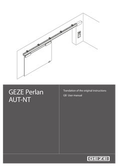
User manual Perlan AUT-NT
… instructions GB User manual … Safety instructions … 6 Operation … Operating modes … Display of the operating mode … Behaviour in the individual operating modes … Symbols and means of representation Symbols and means of representation Warnings In these instructions, warnings are used to warn against material damage and injuries. XX Always read and observe these warnings. XX Observe all the measures that are marked with the warning symbol and warning word. Warning symbol – Warning word Meaning WARNING Danger for persons. Non-compliance can result in death or serious injuries. CAUTION Danger for persons. Non-compliance can result in minor injuries. CAUTION Information on avoiding material damage, understanding a concept or optimising the processes. Further symbols and means of representation Important information and technical notes are emphasised in order to illustrate the correct operation. Symbol Meaning means "important note" means "additional information" XX … Symbol for an action: Here you have to do something. XX Observe the sequence if there are several action steps. Product liability In accordance with the liability of manufacturers for their products as defined in the German "Produkthaftungsgesetz" (Product Liability Act), the information contained in these instructions (product information and proper use, misuse, product performance, product maintenance, obligations to provide information and instructions) is to be observed. Non-compliance releases the manufacturer from its statutory liability. … Intended use The PERLAN AUT-NT sliding door drive is designed for the automatic opening and closing of the sliding leaves. The PERLAN AUT-NT sliding door drive is suitable for use in dry rooms in private areas. The PERLAN AUT-NT sliding door drive may not be used at fire or smoke protection doors and in a hazardous (Ex) area. The PERLAN AUT-NT sliding door drive may not be used to open and close vertical sliding leaves. Any other use than the proper use, such as permanent manual operation, as well as all changes to the product are impermissible. … GEZE Perlan AUT-NT Safety instructions Thoroughly read and abide by this user manual before commissioning the door. In addition, always observe the following safety precautions: àà The prescribed mounting, maintenance and repair work must be performed by properly trained personnel authorised by GEZE. àà The country-specific laws and regulations are to be observed during safety-related tests. àà GEZE shall not be liable for injuries or damage resulting from unauthorised modification of the system. àà GEZE shall not be liable if products from other manufacturers are used with GEZE equipment. àà Only original GEZE parts may be used for repair and maintenance work. àà The connection to the power supply must be made by a professional electrician. Perform the power connection in accordance with DIN VDE 0100-610. àà The electrical installation at the customer has to have an all-pole power disconnector that can be secured reliably against reactivating (e.g. lockable switch with at least … mm contact opening). àà A customer-side 10 A overload cut-out must be used as the line-side disconnecting device. àà Observe the latest versions of guidelines, standards and country-specific regulations, in particular: àà BGR 232 "Guidelines for power-operated windows, doors and gates" àà DIN 18650, Part … Terms Term Drive sides at 1-leaf systems Drive sides at 2-leaf systems Contactors Statement The side of the track on which the drive unit is located, is usually the closing direction of the sliding leaf The side of the track on which the drive unit is located, is usually the opening direction of the sliding leaf Button, switch or motion detector for actuating the sliding door drive. Actuation function in the "Automatic" operating mode Contactor with switch Button for opening and closing the sliding leaf. Actuation function only in the "Automatic" function operating mode. The sliding leaf is opened automatically when the button is first pressed and closed again automatically when the button is pressed the second time. The function can be activated during commissioning by parameter configuration. Push & Go If the sliding leaf is pressed manually out of the closing position during an activated Push & Go function in the "Automatic" operating mode, the sliding leaf opens automatically. Stop Self-locking switch with which immediate stopping of the sliding door drive can be triggered in case of danger. The sliding door drive remains in its current position until the user releases the stop switch again, thus terminating the stop situation. … Structure Structure The sliding door drive shown is only a schematic diagram. For technical reasons, we cannot show all of the possibilities here. The operating elements can be arranged individually. � � � � � � � � … Power pack 230 V / 24 V Flush pull Operating mode LED … Operation … GEZE Perlan AUT-NT Operation The set parameters of the drive functions may only be modified by properly trained persons. Commissioning and the setting or modification of the door parameters as well as of some special drive functions can be carried out by using the DIP switches on the controller (see wiring diagram Perlan AUT-NT, Mat. No. 139997). … Operating modes Dead-man The drive continues to move in the direction as long as its button is pressed or the signal is applied. In case of obstacles the sliding door drive stops. Semi-automatic The drive moves in the direction of the pressed button or of the applied signal. The drive does not close automatically after an opening pulse. It remains in the open position and only closes after a renewed closing command. The sliding door drive stops in case of obstacles, a stop signal or control commands against the current direction of movement. Automatic In addition to the semi-automatic operating mode the sliding door drive closes automatically after the set holdopen time. In the case of obstacles in the closing direction the door opens again and closes automatically after the set holdopen time. In the case of control commands against the current direction of movement the sliding door drive reverses. At a stop signal the sliding door drive stops for the duration of the stop signal. When the stop signal drops again, the door moves further in the direction of movement previously selected. Single permanent opening In order to induce a unique permanent opening in automatic mode the OPEN and CLOSE buttons have to be kept pressed for longer than … Display of the operating mode The operating mode is indicated by the green LED at the operating panel. During an automatic cycle it lights up continuously as long as the sliding door drive is moving. During the hold-open time the LED flashes, in semiautomatic mode the LED flashes during the movement. The red LED flashes rapidly in case of a fault (system fault). Clearing a system fault: XX Press the Reset button for at least … Operation Behaviour in the individual operating modes Automatic State Closed OPEN button 1) Open, wait for holdopen time, close CLOSE button --- Opens Opens further, wait for hold-open time, close Reverses and closes Open Hold-open time is set again Hold-open time is aborted, closes Closes Reverses, opens, wait for Closes further hold-open time, close STOP button 2) Door remains closed, inactive until stop button. An OPEN button actuation remains stored for 20 s. If the stop button becomes inactive within this period, opening is carried out. Door stops, hold-open time is set. If the STOP button becomes inactive within the holdopen time, the door opens further, otherwise the door closes. Door remains open, hold-open time is set again, as long as the button is active. Door stops, if STOP button becomes inactive, the door closes. At obstacle --- Door stops, waits briefly, tries to open further (max. 3×). If opening is not possible, the door closes. --- Reverses, opens, wait for hold-open time, close Starting of the holdopen time if the door is open and the OPEN button inactive 1) possibly additional OPEN actuation sensors at the same terminal 2) higher priority than OPEN button and CLOSE button The Push & Go function behaves like pushing on the OPEN button. If the OPEN and CLOSE buttons are pressed simultaneously: àà Less than … . XX Replace the motor and/or controller if necessary. Self-test – driver fault recog- The power driver no longer outputs a fault – nition defective message Hardware – encoder fault The encoder is not connected correctly or XX Check the encoder connection. XX Replace the motor or controller. is defective XX Replace the power pack. Hardware – voltage impos- The supply voltage lies outside the perXX Replace the controller if necessible missible range sary. Memory – RAM defective A defect has been recognised in the RAM XX Replace the controller. Memory – ROM defective The programme memory has been changed or is defective Memory – EEPROM defec- The data memory is defective tive A fault state is indicated by flashing codes of the two LEDs on the controller: First the red LED flashes rapidly, then it lights up continuously for approx. 20 seconds. During these 20 seconds the green LED flashes in accordance with the fault code x times. The cycle repeats until the user resets the fault. Example: Green LED flashes … 7). Maintenance The owner must ensure that the system functions properly. GEZE offers maintenance contracts with the following services: àà Inspect fastening elements for firm seating àà Carry out miscellaneous adjustment work àà Carry out operational checks àà Check the safety and control equipment of the door system àà Lubricate all the moveable parts XX … If maintenance is required, notify the service technician. Inspection by trained professionals In accordance with the "Guidelines for power-operated windows, doors and gates" (BGR 232 and GUV … ) Section 6, power-operated doors must be inspected for safety by a trained professional before initial commissioning and at least once a year. 10 GEZE Perlan AUT-NT 10 Technical data Technical data Closing speed
PDF | 1 MB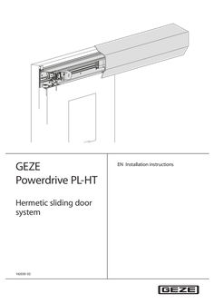
GEZE Powerdrive PL-HT hermetic sliding door system
… instructions Powerdrive PL-HT Table of contents … Safety instructions … Key to symbols In these instructions warnings are used to warn against material damage. XX Always read and observe these warnings! Warning symbol Warning word Meaning WARNING Danger for individuals. Non-compliance can result in death or serious injuries. Important information and technical notes are highlighted to explain the correct operation. Symbol Meaning Means "important note" Means "additional information" XX … Symbol for an action: Here you have to do something. If there are several actions to be taken, keep to the given order. Product liability In accordance with the manufacturer's liability for their products as defined in the German "Produkthaftungsgesetz" (Product Liability Act), the information contained in this brochure (product information and proper use, misuse, product performance, product maintenance, obligations to provide information and instructions) is to be noted and followed. Failure to comply releases the manufacturer from his statutory liability. … Safety instructions àà The mandatory installation, maintenance and repair work must be performed by properly trained personnel authorised by GEZE. àà Components made of stainless steel may not be subjected to high temperatures during working. Discolourations occur at high temperatures in stainless steel. These are permanent and cannot be removed. àà The country-specific laws and regulations are to be observed during safety-related tests. àà GEZE is not liable for any injuries or damage whatsoever resulting from unauthorised changes to the system. àà GEZE is not liable if products from other manufacturers are used with GEZE equipment. àà Furthermore, only original GEZE parts may be used for repair and maintenance work. àà The connection to the power supply must be made by a professional electrician. Perform the power connection and equipment earth conductor test in accordance with VDE 0100 Part 610. àà Use a customer-accessible 10-A overload cut-out as the line-side disconnecting device. àà In accordance with Machinery Directive 2006/42/EC and DIN 18650, before commissioning the door, a safety analysis (risk assessment) must be performed and the door system must be labelled in accordance with CE Marking Directive 98/68/EEC. àà Observe the latest versions of guidelines, standards and country-specific regulations, in particular: àà ASR A1.7 "Guidelines for power-operated windows, doors and gates" àà DIN 18650 "Building hardware – Automatic door systems" àà VDE 0100, Part 610 "Installing Electrical Power Systems with Nominal Voltages up to 1000 V" àà DIN EN 60335-2-103 "Safety of electrical devices for home use and similar purposes; special requirements for drives, for gates, doors and windows" àà Accident-prevention regulations, especially DGUV regulation … Diagrams Number 70722-9-0950 Designation PL-HT installation instructions 160924 Wiring diagram 164883 Wiring diagram supplement 168222 User manual 134358 Safety analysis 108104 Errors and corrective measures The diagrams are subject to change without notice. Use only the most recent version. … St 3.9x32 10 11 11 Installation 12 13 14 12 Powerdrive PL-HT Powerdrive PL-HT Installation 15 16 13 Installation 17 18 14 Powerdrive PL-HT Powerdrive PL-HT Installation 19 15 Installation Powerdrive PL-HT 20 XX XX XX XX Install and connect all the drive components (see installation instructions Powerdrive PL/PI-FR). Connect all the existing operating (e.g. programme switches, etc.), triggering (e.g. movement detectors, etc.) and safety elements (e.g. light curtains, etc.) (see wiring diagram). Install the accessories. Connect the battery to the controller. Soiling in the track results in inferior moving performance of the door, higher noise development and reduces the service life of the carrier rollers. XX Clean the track after mounting. 16 Powerdrive PL-HT … Maintenance Maintenance The general maintenance work for sliding door systems is described in the user manual. This chapter describes supplementary maintenance work for the Powerdrive PL-HT. … Maintenance intervals The owner must ensure that the system functions properly. In order to ensure faultless operation, the door system has to be maintained by a service technician when the maintenance indicator lights up. Door system Powerdrive PL-HT
PDF | 2 MB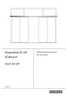
User manual Powerdrive PL-HT / ECdrive H / DCU1-NT-OP
… operating instructions EN User manual DCU1-NT-OP Contents … 3 Operation … Normal operation … Selecting the mode of operation … 10 Blocking and releasing the operating mode … 17 DCU1-NT-OP General safety notices About these instructions Symbols and explanations Important information and technical notes are highlighted to explain correct operation. Symbol Meaning means “important note” means “additional Information” Product liability In accordance with the liability of the manufacturer for its products as defined in the German "Product Liability Act", compliance with the information contained in this brochure (product information and proper use, misuse, product performance, product maintenance, obligations to provide information and instructions) must be ensured. Failure to comply releases the manufacturer from their statutory liability. … General safety notices Carefully read and abide by this user manual before commissioning the door. In addition, always observe the following safety notices: àà Any relevant additional country-specific and European directives must also be observed. àà Operating, maintenance and repair conditions specified by GEZE must be observed. àà Maintenance and repair work may only be performed by properly trained personnel authorised by GEZE. àà GEZE shall assume no liability for damage caused by unauthorised changes to the system. àà Use in dry rooms only. àà The owner is responsible for safe operation of the system. Should safety devices be misaligned, thus preventing them from fulfilling their intended purpose, further operation is not permissible. Inform the service technician immediately in this case. àà In compliance with Machine Directive 2006/42/EC, a safety analysis (risk analysis) must be performed and the door system identified in compliance with CE Identification Directive 93/68/EEC before commissioning the door system. Use the "GEZE safety analysis for automatic sliding doors" here. àà The intervals for safety-related testing are to be complied with based on the country-specific regulations. … Intended use àà The automatic door systems Powerdrive PL-HT and ECdrive H are not intended for the following uses. àà for use in escape and rescue routes àà for use at fire barriers àà The automatic door systems Powerdrive PL-HT and ECdrive H are intended for use in medical areas. àà The automatic door system Powerdrive PL-HT is only intended for use by persons who have been instructed in the function of lowering door leaves and in operating the door handle. The sliding door systems differ in respect of the following functions and features: Linear door leaf movement Sealed closing leaf in closed position Hermetic closing movement: Lowering and pressing of the door leaf against the wall 1-leaf design 2-leaf design Sound proofing … Description Set-up The door system shown is only a schematic diagram. For technical reasons, we cannot show all of the possibilities here. The operating elements can be arranged individually. … Operation … Operation … Normal operation DCU1-NT-OP GEZE sliding doors can be operated with special control elements, which can induce deviating behaviour. Ask the service technician responsible for information on any special control elements which may be installed. … .1 Standard functions (automatic mode of operation) In normal door operation, the door is automatically opened and closed. What happens? An activation device (push button, switch or movement detector) is triggered. Closing safety sensor is interrupted at an opened door. Closing safety sensor is interrupted at a closed door. Closing safety sensor is interrupted while the door is closing. Opening safety sensor is interrupted at a closed door. What does the door do? Door opens and closes again. Door remains open. Door remains closed. Door opens again. Door remains closed. Opening safety sensor is interrupted while the door is opening. Door stops. A person moves toward the opened door and a movement detector is Door remains open. activated. A person moves toward the closing door and a movement detector is Door opens again. activated. Door contacts an obstruction when opening. Door contacts an obstruction when closing. … .2 Door stops, waits and attempts to move to the open position at a reduced speed three times. Then the door closes again. Door reopens immediately, waits the hold-open time and then closes at a reduced speed. Push & Go function One of two Push & Go options can be selected. Push & Go with hold-open time What happens? Doors are pushed open. What does the door do? Doors automatically continue the opening procedure to the learned reduced opening width. The door closes automatically after the set hold-open time. Push & Go without hold-open time What happens? Doors are pushed open. Doors are pushed closed. What does the door do? Doors automatically continue the opening procedure to the learned reduced opening width and remain open. Doors continue the closing procedure automatically to the closed position. àà The functions via the contact sensor for automatic opening are active in Push & Go mode of operation. àà The safety functions with the Push & Go function are identical to the standard function. … .3 Operation Special functions The special functions of the door system are triggered using special switches. Switches/push buttons What does the switch / push button do? Authorised activation device bed opening Door opens to the full opening width and closes again after the hold-open time has expired. Push button nurse opening (activation Door opens to the reduced opening width and closes again after the hold-open device KI/KA) time has expired. Cleaning opening push button (input PE1) Door opens to the full opening width and stays open. When actuated again, the door closes again. Close push button opening (input PE2) Door closes automatically. If a door is used with Push & Go without hold-open time after a manual passing and after the passing it has not closed, the doors can be closed centrally with this push button. Key switch of the programme switch If a key switch is connected to the programme switch, the operation of the programme switch can be locked or released with it Emergency shut off switch (currentless) Door opens and performs the function selected for battery operation: àà Open and switch off àà Close and switch off àà Normal operation for maximum 30 minutes or 30 open/close cycles, then open and switch off àà Normal operation for maximum 30 minutes or 30 open/close cycles, then close and switch off Door closes and remains closed Emergency stop switch … .4 Door stops and can be moved freely by hand Function changes compared to DCU1 NT / DCU1-2-NT The following functions are described in the user manual for Automatic Sliding Door Drives but are not yet available in the version DCU1-NT-OP: àà Limited hold-open setting àà Emergency lock … Operation … DCU1-NT-OP Selecting the mode of operation The programme switches are accessible for everyone without a key switch. As required, access to the programme switch can be restricted to authorised persons by an additional key switch or by assigning a password (ST220). … .1 Display programme switch (DPS) The operating modes can be set at the display programme switch by pressing the respective keys. Operation by unauthorised persons can be blocked as follows: àà Connection of an additional key switch or àà Assignment of a password which can be set in the Service menu of the ST220 Operating mode Key Display OFF Explanation DE GB FR IT Automatic aU aU aU aU Shop closing (one-way operation) ls eO sU sU Permanently open DO hI op pa Door opens and closes again. Inner and outer activation device active. Inner activation device active. Outer activation device only active as long as door is not closed. Door only opens for passage from the inside to the outside. Door remains open. Night No NO NI N- Displayed until door is closed and locked (if lock is present). Na NI NO NI of of of of Off (Service) Full opening width Reduced opening width * 10 + + Door is closed and locked (if lock is present). Movement detector not active. Only authorised activation device is active. The drive is switched to without function for service purposes. The door leaves can be moved freely by hand. Activation and safety sensors are without function. Drive motor and locking are switched off. Door opens the complete opening width. LED off Door opens only part of the possible opening width (can be set). LED lights up. DCU1-NT-OP … .2 Operation Keypad programme switch (TPS) The system operating mode is selected and the corresponding programme is displayed at the keypad programme switch. The desired operating mode of operation can be selected by activating the and keys. The LED of the current mode of operation lights up. Operation by unauthorised persons can be blocked as follows: àà Connection of an additional key switch or àà Assignment of a password which can be set in the Service menu of the ST220 Operating mode Automatic Key Display or m Keypad programme switch TPS Explanation Door opens and closes again. Inner and outer activation device active. m m l m àà Full opening width Door opens over the complete opening width. + àà Reduced opening width + Shop closing (one-way operation) or Door opens only part of the possible opening width (can be set). m m Inner activation device active. Outer activation device only active as long as door is not closed. Door only opens for passage from the inside to the outside. l m m Permanently open or m Door remains open. m m m l Night or m l Door is closed and locked (if lock is present). Movement detector not active. Only authorised activation device is active. m m m 11 Operation … .3 DCU1-NT-OP Mechanical programme switch (MPS, MPS-ST) The desired mode of operation can be set by activating the rotary switch. The marking of the rotary switch must display the desired mode of operation. Programme switch MPS Programme switch MPS-ST The MPS-ST fulfils the same function as the MPS. The desired mode of operation can only be set using the supplied key. The programme switch is blocked when the key is removed. Operating mode Automatic àà Full opening width àà Reduced opening width Shop closing (one-way operation) Permanently open Night Off Setting Explanation Door opens and closes again. Inner and outer activation device active. Door opens the complete opening width. Winter LED goes out. Door opens only part of the possible opening width (can be set). Inner activation device active. Outer activation device only active as long as door is not closed. Door only opens for passage from the inside to the outside. Door remains open. Door is closed and locked (if lock is present). Movement detector not active. Only authorised activation device is active. Drive is deactivated, leaves can be moved by hand. … Blocking and releasing the operating mode … .1 With DPS and TPS – blocking/releasing with additional key switch Turn key switch briefly to block function. àà With the DPS, the function “operation blocked” is signalled by the display "- -" when any key is pressed. àà With the TPS, the function “operation blocked” is signalled by the LED for the respectively set mode of operation flashing once when any key is pressed. XX Turn key switch again briefly for release. Operation is then permanently released. XX 12 DCU1-NT-OP … No mains voltage No mains voltage If the mains voltage fails (e.g. power failure), check the on-site safety fuse first. State Reaction No mains voltage (e.g. power failure) The door remains closed and then locks in "Night" operating mode. Standard drives: In the operating modes shop closing, reduced opening width, full opening width and permanently open, the behaviour of the door depends on the parameters that have been set during the initial commissioning: àà Door remains in the current position and switches off. àà With drives with built-in rechargeable battery depending on the function selected: Mains voltage available again Locking/unlocking without mains voltage active (e.g. power failure) for the toothedbelt lock àà Door closes and switches off. àà Door opens and switches off. àà Normal operation for maximum 30 minutes or 30 open/close cycles, then close and switch off. àà Normal operation for maximum 30 minutes or 30 open/close cycles, then open and switch off. The door automatically returns to the last selected operating mode. Locking only makes sense when the door is closed. Locking with drives with built-in rechargeable battery àà If the door is to be locked and this door is the only point of access: XX Push the door closed manually from the inside. XX Push the locking pin. XX Activate the inner authorised activation device until initialisation of the drive is completed. DPS or TPS indicates Night mode of operation. Door opens – leave the building – door closes – locks again and switches off. Unlocking from the outside with drives with built-in rechargeable battery XX Activate the outer authorised activation device until the drive is initialised and the door starts to open. Door opens – door closes – locks again and switches off. Unlocking from the inside with drives with built-in rechargeable battery: XX Activate the outer authorised activation device until the drive is initialised and the door starts to open. Door opens – door closes – locks again and switches off. Unlocking with drives without built-in rechargeable battery (only possible from the inside) XX Push the door to the desired locking position and push the locking pin (10, Chapter … TPS/DPS Display keypad programme switch Designation – – – – – – – – – – – – x x – – x x x – – – x – x x – x – x x – x x x – – x x x x x x x x – – – x x x x x – – x – – x – x – x – – – – – – x x – – – – No operating voltage Drive too hot Position SIS Motor Activation longer than … What to do if...? Problem Door only opens and closes slowly Door opens and closes constantly Cause Floor guide area dirty Remedy XX Disconnect power supply (emergency control or on-site safety fuse). XX Clean floor guide area. XX Remove obstruction and check door leaf for ease of moveObstruction in travel path ment. Closing safety sensor (SIS) interrupt- XX Clean closing safety sensor (SIS) (light barrier). XX Check settings of light curtain. ed or misaligned Obstruction in sliding path, e.g. stone XX Disconnect power supply (emergency control or on-site safety fuse). in floor guide area XX Clear obstruction and clean floor guide area. XX Check detection field of movement detectors. Light beams or reflections, e.g. reflective floor, drops of rain, plants / flower pots, posters/displays or similar in the scanned area of the movement detector XX Check detection field of movement detectors. Misaligned movement detector Door only opens a crack Obstruction in travel path XX Door does not open Obstruction in travel path XX Movement detector misaligned or defective (inside and/or outside) Operating mode "Night", "OFF" XX Remove obstruction and check door leaf for ease of movement. Remove obstruction and check door leaf for ease of movement. Check movement detector. XX Select another operating mode. "Shop closing" operating mode XX Select "Automatic" operating mode. 14 DCU1-NT-OP Problem What to do if...? Cause Floor locks are locked Remedy XX Unlock floor locks. Lock M is locked XX Unlock hook bolt lock. No mains voltage (e.g. power failure) See Chapter 4, No mains voltage Door does not unlock or lock Door does not close Locking defective Unlock/lock the door manually: XX Check locking in the "Night" operating mode If the locking is defective: XX Notify a service technician. Closing safety sensor (SIS) interrupt- XX Clean the closing safety sensor (SIS). XX Check settings of light curtain. ed or misaligned XX Remove obstruction and check door leaf for ease of moveObstruction in travel path ment. X X Check movement detector. Movement detector triggers constantly Operating mode "Permanently open", XX Select another operating mode. "OFF" No mains voltage (e.g. power failure) See Chapter 4, No mains voltage Programme switch cannot Programme switch is blocked be operated Programme switch is defective Fault messages displayed Fault in the door system at programme switch Turn key switch. Enter password. XX Request servicing. See Chapter 5, Fault messages XX XX Carry out a reset/delete the fault memory àà TPS: XX Use key or to change to the mode of operation OFF (see Chapter … s. The function is not possible with DPS without OFF key. The fault memory is deleted. XX Re-select mode of operation. 15 Cleaning and maintenance DCU1-NT-OP … 7) Wipe with damp cloth. Do not use a cleaning agent. Maintenance àà The owner must ensure that the system is working perfectly. In order to ensure faultless operation, the door system has to be maintained by a service technician when the maintenance indicator lights up. The maintenance indicator is located on the programme switch. The version differs depending on the programme switch used: Programme switch TPS MPS, MPS-ST DPS Maintenance indicator "Reduced opening width" LED flashes. LED flashes. A red dot appears at the bottom right of the display. The maintenance display lights up after the specified calendar period or number of opening cycles, depending on what occurs first: àà Calendar period: … year àà Opening cycles: 500,000 GEZE offers maintenance contracts with the following services: àà Cleaning and readjustment of carrier rollers and tracks àà Inspection and adjustment of toothed belts àà Inspection of door suspension plate and floor guide àà Inspection of fixing elements for firm fit àà Performance of miscellaneous adjustment work àà Performance of operational checks … and àà EN 16005 “Power operated pedestrian doorsets”, Chapter … .1 the safe condition of power operated doors must be checked before initial commissioning, after material changes, and once a year by a professional authorised by GEZE. GEZE offers the following services: Inspection and functional checks of all safety and control equipment in compliance with the requirements in the test log for power-operated windows, doors and gates; Sliding doors and sliding gates BGG 950 (ZH 1/ … General data Powerdrive PL-HT Opening speed Closing speed Electrical connection values Connected load Protection Current consumption for external devices Voltage in emergency battery operation Temperature range IP rating ECdrive H
PDF | 573 KB